LED support

A technology of LED bracket and metal base, which is applied in the direction of semiconductor devices, electrical components, circuits, etc., can solve the problem of restricting the molding of potting glue and the angle of light output of devices, which cannot meet the optical design, and is not conducive to the direct lamination molding process without potting Application and other issues

Active Publication Date: 2014-05-14
LEDMAN OPTOELECTRONICS
View PDF4 Cites 8 Cited by
  • Summary
  • Abstract
  • Description
  • Claims
  • Application Information

AI Technical Summary

Problems solved by technology

[0003] Although the bowl and cup structure 16 is beneficial to the potting of traditional glue, it also limits the molding of the potting glue and the light output angle of the device
With the wide application of LEDs, the optical design of packaged devices is bec

Method used


Image

  • LED support
  • LED support
  • LED support

Examples


Embodiment Construction

[0036] In order to facilitate the understanding of the present invention, the present invention will be described more fully below with reference to the associated drawings. Preferred embodiments of the invention are shown in the accompanying drawings. However, the present invention can be embodied in many different forms and is not limited to the embodiments described herein. On the contrary, these embodiments are provided to make the understanding of the disclosure of the present invention more thorough and comprehensive.

[0037] It should be noted that when an element is referred to as being “fixed” to another element, it can be directly on the other element or there can also be an intervening element. When an element is referred to as being "connected to" another element, it can be directly connected to the other element or intervening elements may also be present.

[0038] Unless otherwise defined, all technical and scientific terms used herein have the same meaning as...


PUM


Abstract

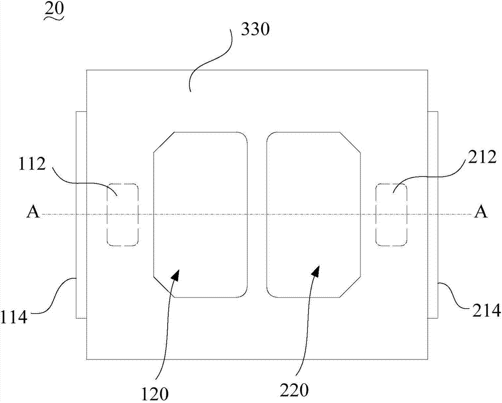
An LED support comprises a first electrode, a second electrode and injection molding plastic parts. The first electrode comprises a first metal base and a first meal welding disk. The first metal welding disk is fixed onto the first metal base, and one side of the first metal welding disk protrudes out of one side of the first metal base. A first injection molding hole is formed in the first metal base. The second electrode and the first electrode are arranged at an interval, the second electrode comprises a second metal base and a second metal welding disk, the second metal welding disk is fixed onto the second metal base, one side of the second metal welding disk protrudes out of the side, close to the first electrode, of the second metal base, and the second metal welding disk and the first metal welding disk are arranged at an interval. A second injection molding hole is formed in the second metal base. The injection molding plastic parts comprise first injection molding portions, second injection molding portions and third injection molding portions, wherein the first injection molding hole is filled with the first injection molding portions, the space between the two bases is filled with the second injection molding portions and the third injection molding portions are arranged on the first metal base, the second metal base, the first injection molding portions and the second injection molding portions. The third injection molding portions and the surfaces, far away from the first metal base, of the metal welding disks form a plane structure. The light outlet angle of the LED support is not limited.

Description

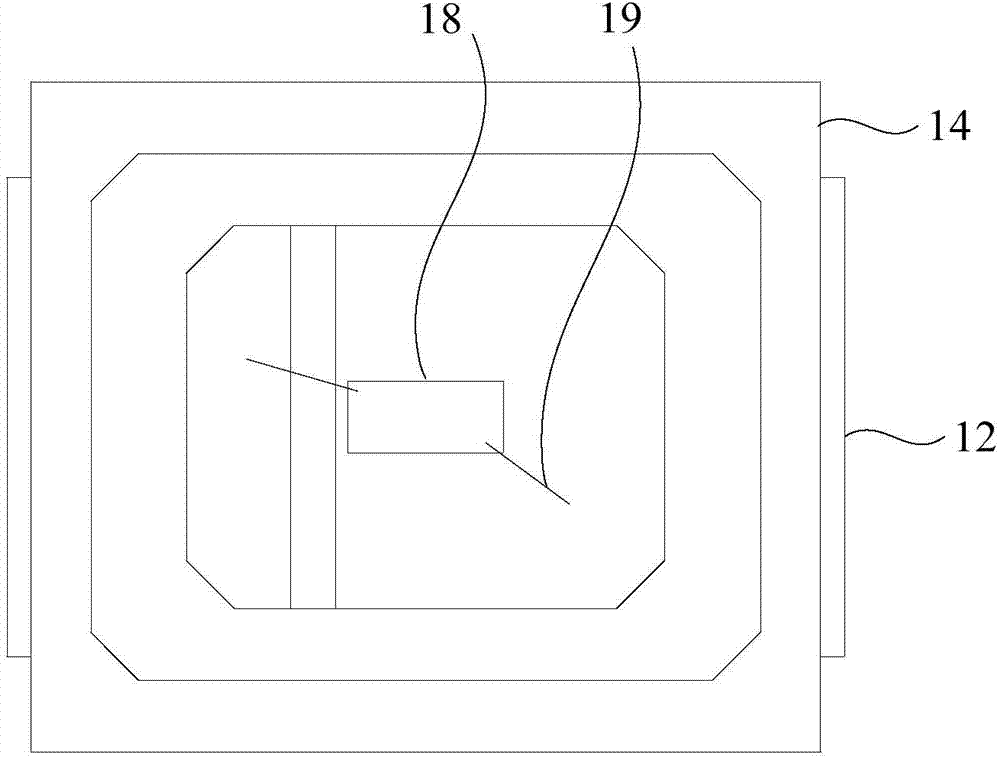
technical field [0001] The invention relates to the technical field of LED packaging, in particular to an LED bracket. Background technique [0002] Such as figure 1 and figure 2 As shown, a conventional LED bracket 10 generally includes a metal skeleton portion 12 and an injection molded plastic portion 14 . The injection molded plastic part 14 is indented to form a bowl cup structure 16 with a certain optical angle, so as to facilitate the potting of glue and the light emission of the LED chip 18 . The LED chip 18 is generally bonded to the metal skeleton part 12 at the bottom of the bowl structure 16 through epoxy resin, silica gel or silver glue and other primers, and leads the wire 19 and the LED bracket at the electrode above the LED chip 18 through Banding technology. The positive and negative electrodes of 10 are connected to each other to play the role of electrical connection. [0003] Although the bowl and cup structure 16 is beneficial to the potting of trad...

Claims


Application Information

Patent Timeline
IPC IPC(8): H01L33/48H01L33/62H01L33/54
CPCH01L2224/48091H01L2224/48247H01L2224/48257H01L33/483H01L33/54H01L33/62
Inventor 李漫铁屠孟龙李扬林
Owner LEDMAN OPTOELECTRONICS
Why Eureka
Try Eureka