Truss Shearing Mechanism of Triangular Truss Production Line

A shearing mechanism and production line technology, applied in the field of truss shearing mechanism, can solve problems affecting the straightness of trusses, deformation of triangular trusses, easy damage of brakes, etc., and achieve the effects of prolonging service life, small impact on power grid, and low power

Active Publication Date: 2015-11-18
TJK MACHINERY TIANJIN
View PDF9 Cites 0 Cited by
  • Summary
  • Abstract
  • Description
  • Claims
  • Application Information

AI Technical Summary

Problems solved by technology

The defect of the hydraulic horizontal direct push shearing method is: because the whole truss is cut with a movable knife, the whole truss is seriously bent at the cutting head, which affects the straightness of the truss
The defect of the eccentric slider swing shearing method is: because a movable knife is used to cut the entire truss, the whole truss is seriously bent at the cutting end, which affects the straightness of the truss; in addition, the intermittent start and stop of the motor reducer has a large impact on the power grid , the brake is easily damaged, and the motor power is large
The disadvantage of the hydraulic shearing method is: firstly, the corresponding scissors on one end of the two shearing arms are used to relatively move and simultaneously shear the truss, causing the distance between the two tendons of the triangular truss to be reduced, that is, the inner width of the triangular truss is narrowed, cause the deformation of the triangular truss; secondly, the shape of the scissors on one end of the two shearing arms is triangular scissors, and the sharp corners of the two triangular scissors are opposite to each other. Driven by the double piston rods of the hydraulic cylinder, the two triangular scissors move relatively. The sharp corners of the two triangular scissors are in contact to complete the shearing of the triangular truss. During the cutting process, the sharp corners of the two scissors frequently collide, causing the scissors to be damaged.

Method used


Image

  • Truss Shearing Mechanism of Triangular Truss Production Line
  • Truss Shearing Mechanism of Triangular Truss Production Line
  • Truss Shearing Mechanism of Triangular Truss Production Line

Examples


Embodiment Construction

[0023] Embodiments of the present invention will be further described below in conjunction with the accompanying drawings.

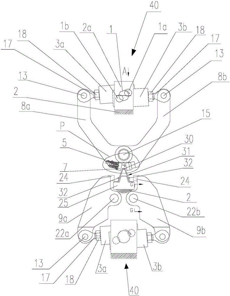
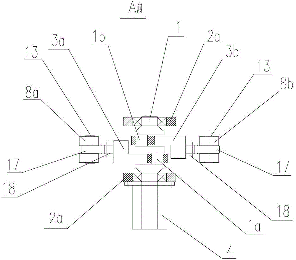
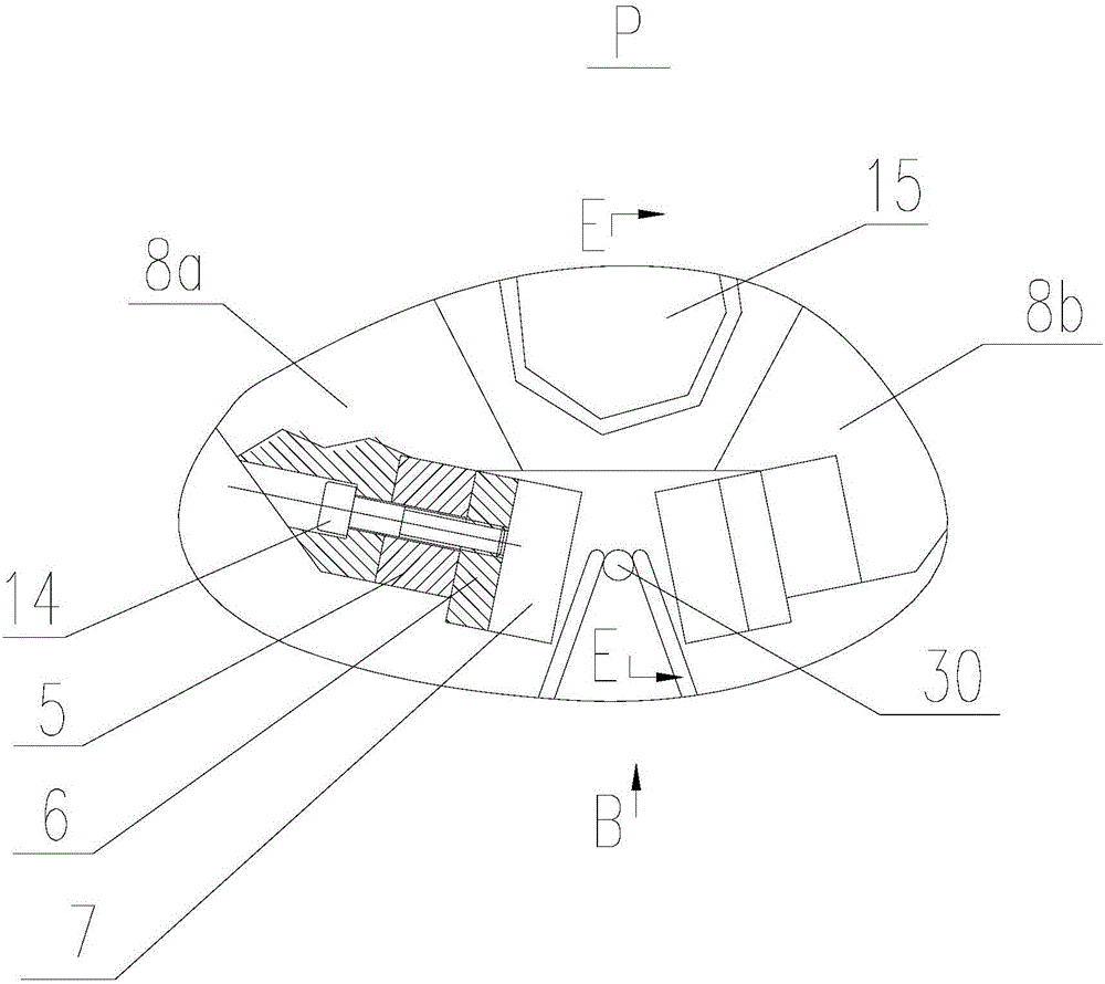
[0024] figure 1 is the front view of the present invention; figure 2 Yes figure 1 A-direction view; image 3 Yes figure 1 Enlarged view of part P in the middle; Figure 4 Yes image 3 Enlarged view in B direction; Figure 5 Yes image 3 Middle E-E sectional view; Image 6 Yes figure 1 G-G sectional view of ; Figure 7 Yes figure 1 The view from the direction D in the middle shows that the two lower scissors cut the two lower chord ribs respectively along the lower fixed scissors.

[0025] like figure 1 As shown, the triangular truss 31 includes: an upper spiral 30, two lower spirals 32, and two zigzag abdominal ribs respectively fixed on the sides of the upper spiral 30 and the two downward spirals 32 (no serial numbers are marked in the figure) .

[0026] The present invention provides a truss shearing mechanism on a triangular truss prod...


PUM


Abstract

The invention discloses a truss shearing mechanism of a triangular truss production line. The truss shearing mechanism of the triangular truss production line structurally comprises an upper shearing device and a lower shearing device. According to the upper shearing device, two upper shearing arms are hinged to an upper hinged shaft, upper scissors are installed at the corresponding ends of the upper shearing arms, the other end of each upper shearing arm is hinged to a crankshaft driving mechanism, and the crankshaft driving mechanism drives the two upper shearing arms to shear an upper spiral rib. The lower shearing device comprises two lower shearing arms, wherein the lower shearing arms are hinged to a first lower hinged shaft and a second lower hinged shaft respectively, lower scissors are installed at the corresponding ends of the lower shearing arms, the other ends of the lower shearing arms are hinged to the two sides of the crankshaft driving mechanism, and the crankshaft driving mechanism drives the two lower shearing arms to shear a lower spiral rib. The truss shearing mechanism of the triangular truss production line has the advantages that power is low, impact on a power grid is low, the structure is simple, and the cost is low; the phenomenon that the two pairs of scissors collide with each other is avoided, the service life is long, and the quality of a sheared truss is improved; a cut of the lower spiral rib is flat after the lower spiral rib is sheared, and the phenomenon that due to the fact that the width of the inner side of the triangular truss becomes narrower, the defect of deformation of the triangular truss is avoided.

Description

technical field [0001] The invention relates to a triangular truss production line, in particular to a truss shearing mechanism of the triangular truss production line. Background technique [0002] At present, most of the domestically produced trusses are triangular trusses with a triangular cross-section. The triangular trusses include: one upper spiral, two lower spirals, and two Zigzag abdominal muscles. The shear mechanism in the triangular truss production line usually includes the following three forms: [0003] The first is the hydraulic horizontal direct push shearing method, its structure includes: a hydraulic cylinder, the hydraulic cylinder body is fixed on the frame, the piston rod of the hydraulic cylinder is connected to a movable knife seat equipped with a movable knife; The knife seat is fixed on the frame; driven by the hydraulic cylinder, the movable knife moves along the side of the fixed knife to shear the triangular truss. The defect of the hydraulic...

Claims


Application Information

Patent Timeline
Patent Type & Authority Patents(China)
IPC IPC(8): B21F11/00
Inventor 陈振东
Owner TJK MACHINERY TIANJIN
Why Eureka
Try Eureka