Cavity plate positioning mechanism

A technology of positioning mechanism and master template, which is applied in the field of positioning mechanism, can solve problems such as failure to work, material head stuck, spring back of the master template, etc., to achieve the effect of convenient removal and full-automatic production

Inactive Publication Date: 2014-05-21
MITAC PRECISION TECH(KUNSHAN) CORP
View PDF11 Cites 1 Cited by
  • Summary
  • Abstract
  • Description
  • Claims
  • Application Information

AI Technical Summary

Problems solved by technology

[0004] 1. After the master formwork springs back, the distance between the mother formwork and the stripping plate becomes smaller, and the material head will be stuck, making it impossible to take out the material head;
[0005] 2. Some special molds, such as robot automatic insert molding (insert molding), if the insertion position is in the master mold, the position of the master mold is not fixed due to springback, and the robot will not be able to position and cannot work
[0006] In view of this, it is necessary to develop a female template positioning mechanism to solve the above-mentioned springback problem of the female template when the male template and the female template are opened in the three-plate mold.

Method used


Image

  • Cavity plate positioning mechanism
  • Cavity plate positioning mechanism
  • Cavity plate positioning mechanism

Examples


Embodiment Construction

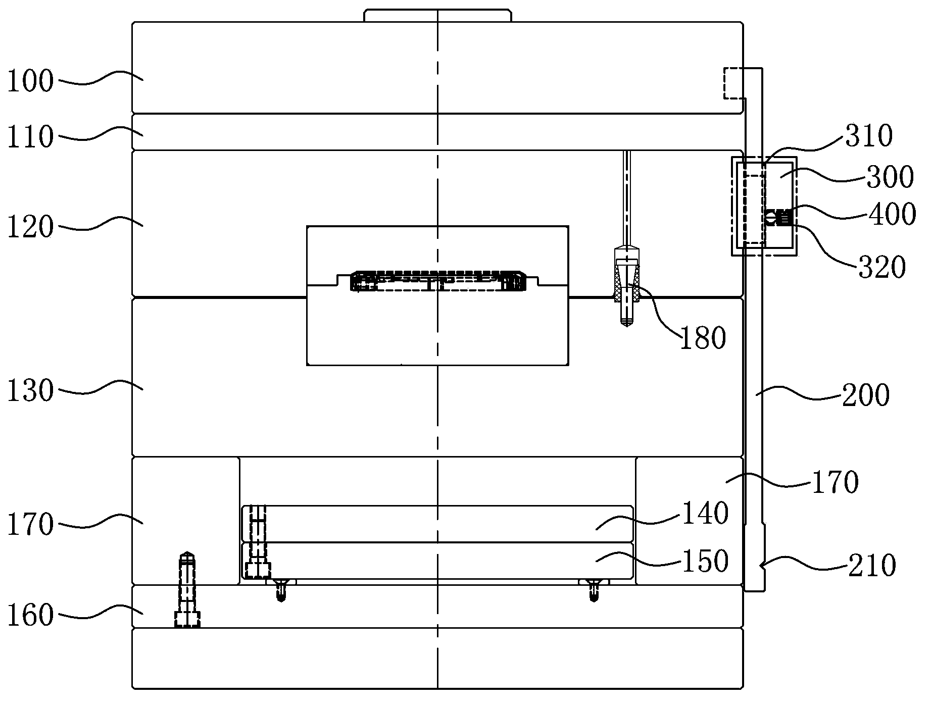
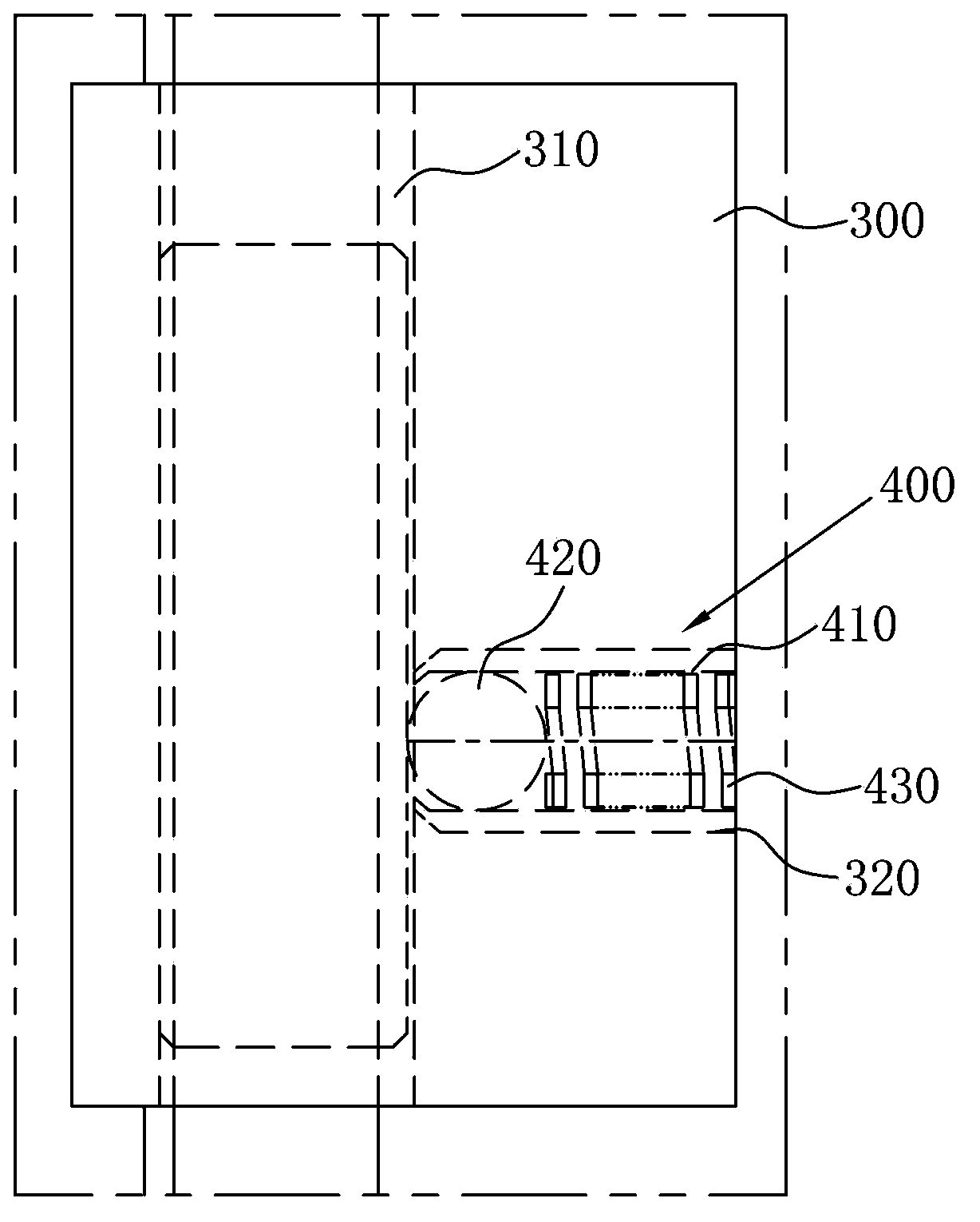
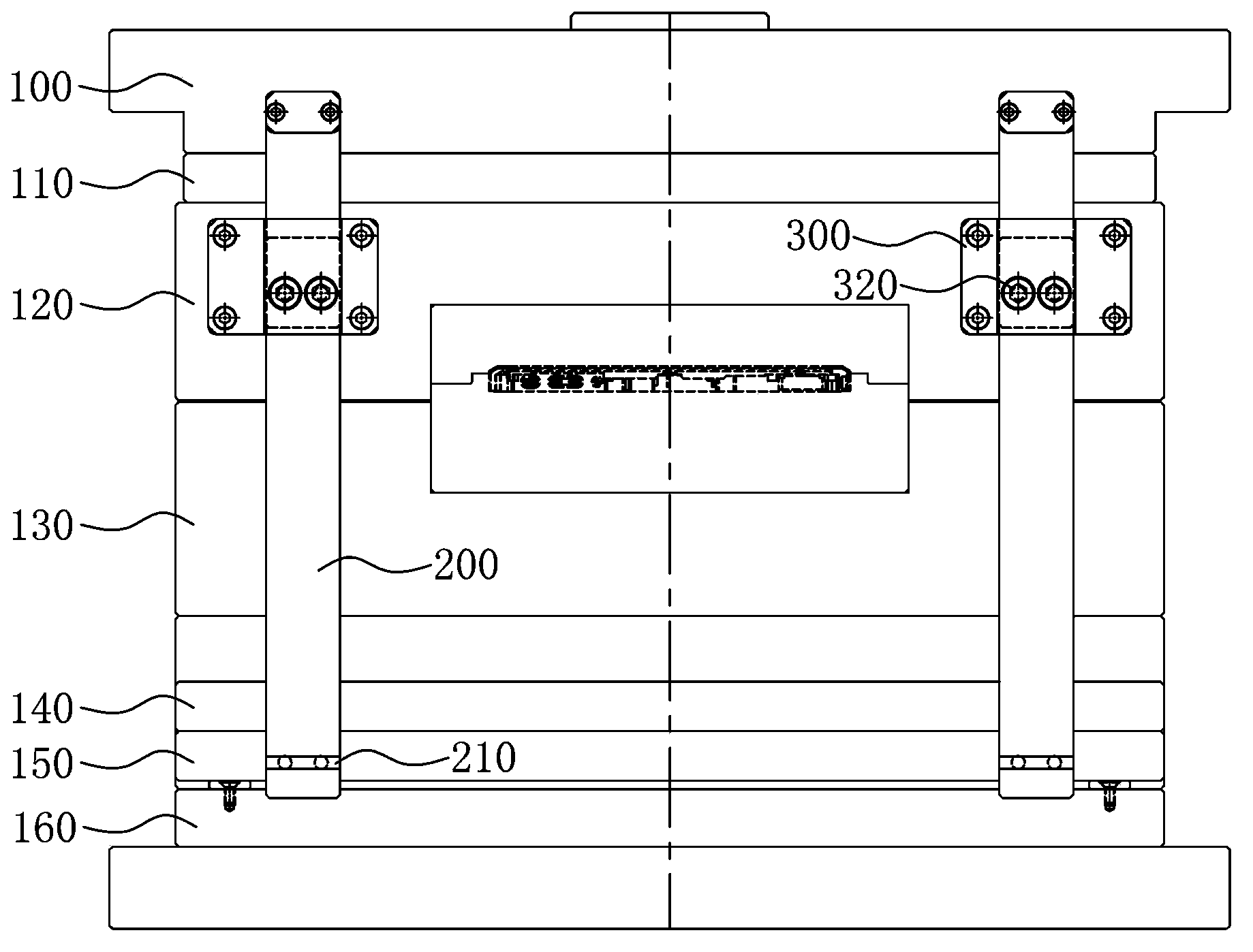
[0026] Please refer to figure 1 , figure 2 and image 3 shown, where figure 1 A schematic diagram showing an angle of the positioning mechanism of the master template of the present invention in the mold clamping state, figure 2 painted figure 1 The partial enlarged schematic diagram of the image 3 It shows another perspective schematic view of the positioning mechanism of the master template of the present invention in the state of mold clamping.

[0027] The female template positioning mechanism of the present invention is applied to a three-plate mold, and the three-plate mold includes: an upper fixing plate 100, a stripping plate 110, a female template 120, a male template 130, an upper ejector plate 140, and a lower ejector plate 150 , the lower fixed plate 160 and the two-foot pad 170 between the male template 130 and the lower fixed plate 160, take the mold opening direction as the vertical direction, in this embodiment, the female template positioning mechanism...


PUM


Abstract

The invention relates to a cavity plate positioning mechanism, which is applied to a three-plate die. The cavity plate positioning mechanism comprises a guide rod, a bearing plate and at least one marble structure, wherein one end of the guide rod is fixedly arranged on an upper fixed plate of the three-plate die, and at least one clamp slot is formed in the guide rod; the bearing plate is fixed on a cavity plate of the three-plate die, the die opening direction of the die is a vertical direction, the bearing plate is provided with a vertical through hole which is used for the guide rod to penetrate through, the bearing plate is also provided with at least one horizontal hole which is perpendicularly intersected with the vertical through hole; the at least one marble structure is arranged in the horizontal hole and consists of a shell, a marble in the shell, and an elastic element in the shell, and the elastic element is arranged at the inner bottom of the shell and supports against the marble. According to the cavity plate positioning mechanism, when the cavity plate is subjected to die opening to the maximum stroke, the marble is bounced out by the elastic element and is clamped in the clamp slot and positioned by the cavity plate, so that the phenomenon that the cavity plate bounces back when a core plate and a cavity plate in the three-plate die are subjected to die opening can be overcome.

Description

【Technical field】 [0001] The invention relates to a positioning mechanism, in particular to a positioning mechanism for a mother template used in a three-plate mold. 【Background technique】 [0002] The plastic parts of the product will be molded using plastic molds, such as plastic parts such as housings of electronic products. Due to the popularity of electronic products, the improvement of plastic molds has also become a subject of extensive research. [0003] In the production of plastic parts, for example, three-plate molds are often used in the case of needle-point injection, multiple holes in one mold, or offset injection points. In order to ensure the mold opening sequence of the three-plate mold, auxiliary mechanisms such as shutters and small tie rods will be set in the three-plate mold. When the female template of the three-plate mold is separated from the male template, under the action of the small tie rod of the mold, the female template will rebound, and the ...

Claims


Application Information

Patent Timeline
Patent Type & Authority Applications(China)
IPC IPC(8): B29C45/26B29C33/30
CPCB29C45/2606
Inventor 谢苇苇
Owner MITAC PRECISION TECH(KUNSHAN) CORP
Why Eureka
Try Eureka