
Vibration isolation device without angular displacement and its branch chain

An angular displacement and vibration isolation technology, applied in the direction of non-rotation vibration suppression, etc., can solve the problems of image quality degradation, large measurement error, increase the image displacement of the camera system, etc., and achieve the effect of vibration isolation without angular displacement.

Inactive Publication Date: 2015-08-12
HENAN UNIV OF SCI & TECH
View PDF6 Cites 0 Cited by
  • Summary
  • Abstract
  • Description
  • Claims
  • Application Information

AI Technical Summary

Problems solved by technology

Compared with linear vibration, angular vibration will double the image shift of the camera system, reduce the image quality, and reduce the resolution of the optical system. Therefore, the impact of angular vibration on imaging quality is much greater than that of linear vibration. Not only that, the rotation of the optoelectronic platform caused by vibration will cause the coordinate system of the optoelectronic platform to rotate relative to the coordinate system of the aircraft, making the measurement of the optoelectronic platform with measurement function inaccurate and causing large measurement errors

Method used


Image

  • Vibration isolation device without angular displacement and its branch chain
  • Vibration isolation device without angular displacement and its branch chain
  • Vibration isolation device without angular displacement and its branch chain

Examples


Embodiment Construction

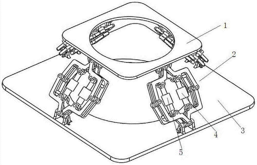
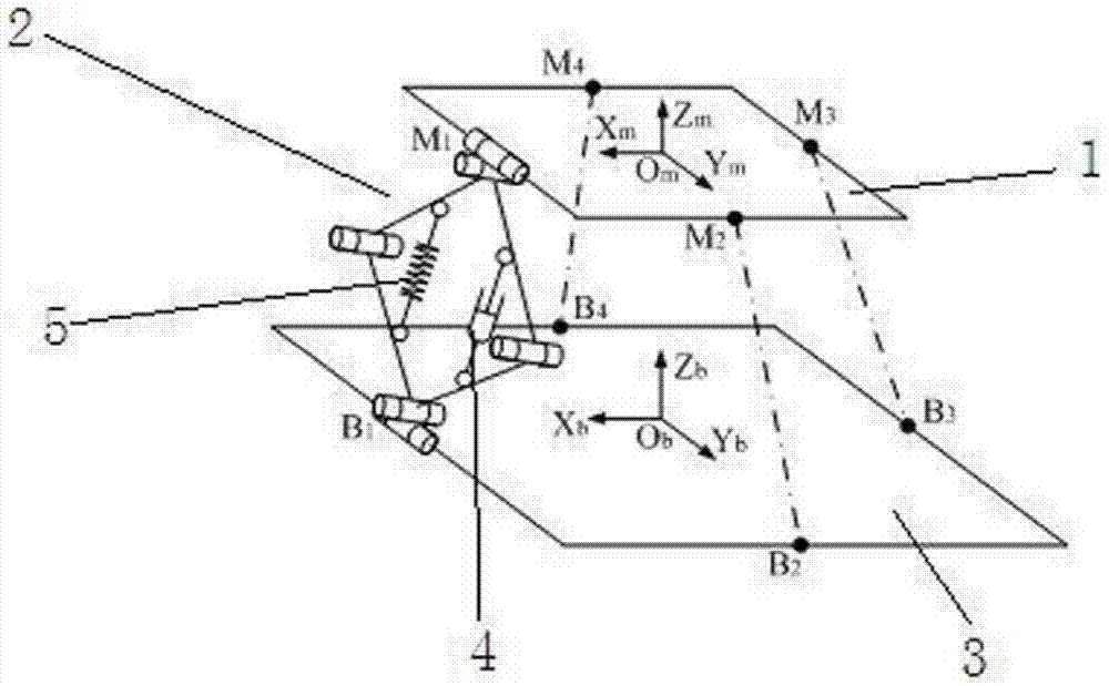
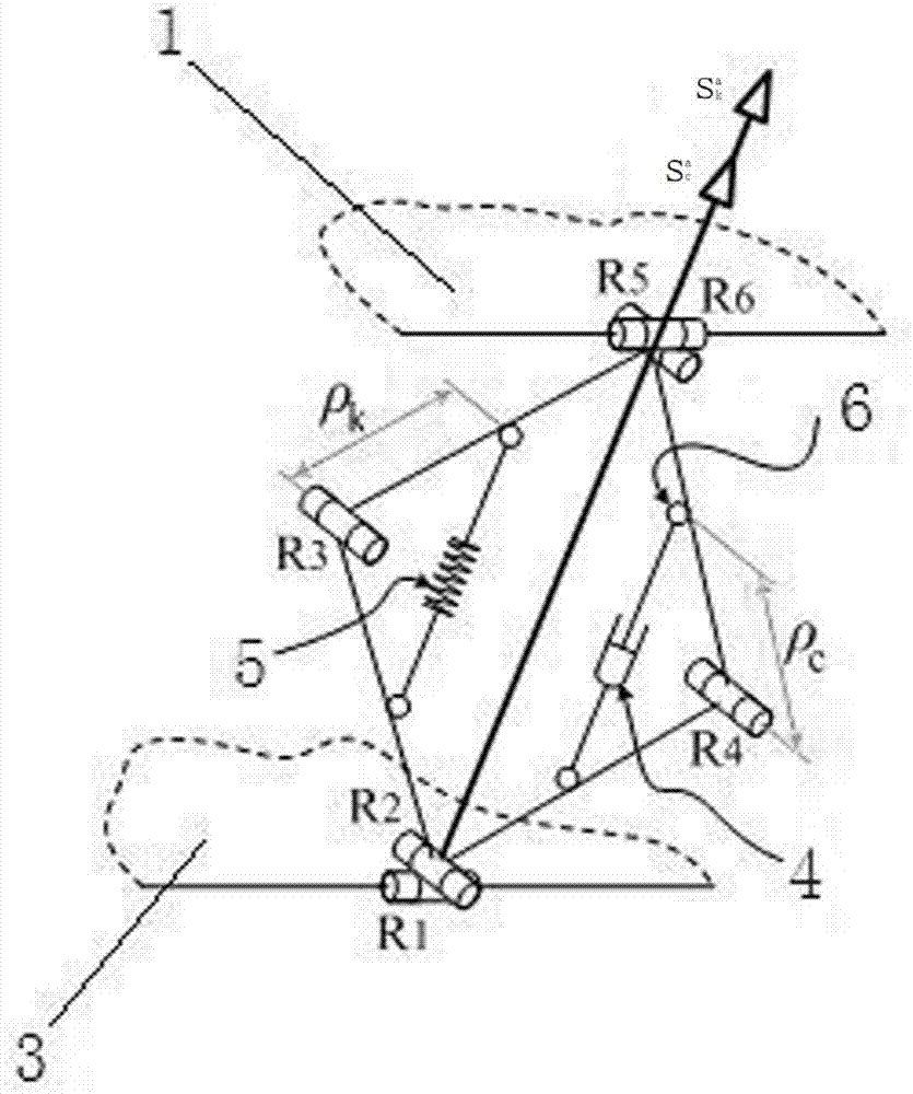
[0022] Examples of vibration isolation devices without angular displacement are Figure 1~4 Shown: Including the moving platform 1 and the fixed platform 3, the moving and fixed platforms are connected by four branch chains 2, the four branch chains are evenly arranged in the circumferential direction, and the structure of each branch chain is the same, and only the structure of one of the branch chains is shown below to describe. The branch chain includes the first rotating pair R6 and the second rotating pair R5 whose axes are perpendicular to each other, the third rotating pair R2 and the fourth rotating pair R1 whose axes are perpendicular to each other, the axes of the second and third rotating pairs are parallel to each other, the first, The axes of the fourth revolving pair are parallel to each other, the first and second revolving pairs constitute the first Hooke hinge, the third and fourth revolving pairs form the second Hooke hinge, and each fourth revolving pair R1 ...


PUM


Abstract

The invention relates to a non-angular-displacement vibration isolating device and a branch chain thereof. The branch chain comprises a first rotating pair, a second rotating pair, a third rotating pair and a fourth rotating pair, wherein the axis of the first rotating pair is perpendicular to the axis of the second rotating pair, the axis of the third rotating pair is perpendicular to the axis of the fourth rotating pair, the first rotating pair is connected with a movable platform, the fourth rotating pair is connected with a fixed platform, the axis of the second rotating pair is parallel to the axis of the third rotating pair, and the axis of the first rotating pair is parallel to the axis of the fourth rotating pair. The branch chain further comprises a fifth rotating pair and a sixth rotating pair, the axis of the fifth rotating pair and the axis of the sixth rotating pair are parallel to the axis of the second rotating pair, the second rotating pair is connected with the sixth rotating pair through a first connecting rod, the sixth rotating pair is connected with the third rotating pair through a second connecting rod, the third rotating pair is connected with the fifth rotating pair through a third connecting rod, the second rotating pair is connected with the sixth rotating pair through a fourth connecting rod, and the plane where the axis of the second rotating pair and the axis of the sixth rotating pair are located is parallel to the plane where the axis of the third rotating pair and the axis of the fifth rotating pair are located. The non-angular-displacement vibration isolating device capable of converting the angular displacement into linear displacement and the branch chain used in the non-angular-displacement vibration isolating device are provided.

Description

technical field [0001] The invention relates to a non-angular displacement vibration isolation device and its branch chain in the field of vibration isolation. Background technique [0002] With the development of aviation technology, the resolution requirements of photoelectric imaging systems are getting higher and higher. In many high-resolution aerial photoelectric imaging systems, although high-quality sensors are used, the image quality obtained is not ideal, which limits The main factor of high-resolution imaging is often not caused by electrical or optical systems, this image blur degradation is mainly caused by aviation vibration. The optoelectronic platform is a device installed on the aircraft or vehicle for the purpose of stabilizing photoelectric equipment, reconnaissance, search and rescue, etc. The optoelectronic platform uses the aircraft or vehicle as the carrier. In a series of complex and random vibration environments such as , wind resistance torque and ...

Claims


Application Information

Patent Timeline
Patent Type & Authority Patents(China)
IPC IPC(8): F16F15/04
Inventor 刘延斌韩秀英马佳佳尹晨旭
Owner HENAN UNIV OF SCI & TECH
Learn More