Photolytic catalytic purification device and corresponding process for treating pharmaceutical waste gas

A technology of photolysis catalysis and purification device, applied in the direction of using liquid separating agent, chemical instruments and methods, dispersed particle filtration, etc., can solve the problem of excessive treatment cost and investment cost, low treatment rate of factory waste gas, and long biological treatment time. and other problems, to achieve the effect of fast deodorization rate, easy control of process flow and simple structure

Inactive Publication Date: 2014-05-28
河北欧美环境工程有限公司
View PDF8 Cites 11 Cited by
  • Summary
  • Abstract
  • Description
  • Claims
  • Application Information

AI Technical Summary

Problems solved by technology

[0004]1. The exhaust gas in the factory production is generally only discharged into the air after simple treatment such as simple water spray equipment or activated carbon adsorption, and the exhaust gas often does not meet the standard , containing toxic and odorous substances, will still pollute the environment and endanger human health; in addition, some chemical products will be mixed in the exhaust gas and discharged, and the yield will be affected
[0005]2. Due to the technical problems of the treatment facilities themselves, the treatment rate of factory waste gas is not high or the treatment cost and investment cost are too high
In this treatment method, the biological treatment takes a long time and the treatment capacity is small, and it is powerless to deal with a large amount of waste gas discharged from some continuous production factories; in addition, the organic waste gas treatment device is aimed at organic waste gas, and cannot treat some inorganic polluting gases to reach the national level. emission standards

Method used


Image

  • Photolytic catalytic purification device and corresponding process for treating pharmaceutical waste gas
  • Photolytic catalytic purification device and corresponding process for treating pharmaceutical waste gas
  • Photolytic catalytic purification device and corresponding process for treating pharmaceutical waste gas

Examples


Embodiment 1

[0042] Example 1 A photocatalytic purification device for treating pharmaceutical waste gas

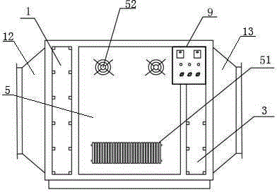
[0043] Such as figure 1 As shown, this embodiment is a photocatalytic exhaust gas purification device for treating pharmaceutical exhaust gas, including a box body 7 and a pre-filter system 1, a UV photolysis system 2, and a filter system that are arranged in the box body 7 and communicated in sequence. Exhaust system 5, rear deodorization system 3, and a control panel 9 is also provided on the side wall of the box body 7.

[0044] The pre-filter system 1 is provided with a first filter screen 10 , the first filter screen 10 is arranged at the air inlet 12 of the box body 7 , is fixed in the box body 7 , and extends along the width direction of the box body 7 .

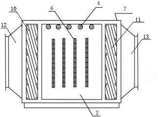
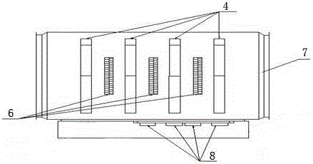
[0045] Such as figure 2 and image 3As shown, the UV photolysis system 2 is located in the middle of the box body 7 and includes an ultraviolet lamp 4 , a second filter screen 6 , and an electronic ballast 8 . A plura...

Embodiment 2

[0050] Example 2 A pharmaceutical waste gas treatment process

[0051] The pharmaceutical waste gas treatment process is carried out in the following steps:

[0052] ⑴The gas volume is 60000 m 3 After the exhaust gas per hour is preliminarily dedusted by a water film dust collector with a diameter of φ2.4×7.0m under a negative pressure of 0.03MPa, the gas A1 is obtained;

[0053] (2) Gas A1 enters the photocatalytic purification device for treating pharmaceutical waste gas provided in Example 1 through the water film dust collector, and enters the UV photolysis unit for 0.7s under the action of the component pre-filter unit to obtain gas B1;

[0054] (3) The gas B1 is drawn out by the negative pressure of the centrifugal induced draft fan, and sent into the chimney to meet the standard discharge.

[0055] The waste gas deodorization rate treated in this embodiment is 99.4%, the waste gas treatment capacity is large, the deodorization rate is fast, the dust residue is low, ...

Embodiment 3

[0056] Example 3 A pharmaceutical waste gas treatment process

[0057] The pharmaceutical waste gas treatment process is carried out in the following steps:

[0058] ⑴The gas volume is 21000 m 3 / h exhaust gas passes through the filter area of ​​378m 3 , processing capacity is 21000 m 3 After preliminary dust removal by the bag filter in / h, gas C1 is obtained;

[0059] (2) Gas C1 enters the photocatalytic purification device for treating pharmaceutical waste gas provided in Example 1 through the bag filter, and enters the UV photolysis unit for 0.7s under the action of the pre-filter unit of the component to obtain gas D1;

[0060] (3) The gas D1 is drawn out by the negative pressure of the centrifugal induced draft fan, and sent into the chimney to meet the standard discharge.

[0061] The waste gas deodorization rate treated in this embodiment is 99.3%, the waste gas treatment capacity is large, the deodorization rate is fast, the dust residue is low, the process flow...


PUM

PropertyMeasurementUnit
Wavelengthaaaaaaaaaa

Abstract

The invention discloses a photolytic catalytic purification device for treating pharmaceutical waste gas, which comprises a box, and a front filter system, a UV photolysis system with UV lamp tubes and a rear deodorization system which are communicated in sequence with the interior of the box, wherein second filter screens are arranged between the UV lamp tubes; the UV lamp tubes are connected with electronic ballasts through wires. The photolytic catalytic purification device is simple in structure, high in applicability and low in operation cost, generates no noise, occupies a small area, and saves space. The invention further discloses a corresponding process for treating pharmaceutical waste gas. After being subjected to dust removal by a dust remover and conversion by the photolytic catalytic purification device, the waste gas is discharged by a centrifugal induced draft fan, and pollutants such as volatile organic compounds (VOC), hydrogen sulfide, ammonia gas and thiol can be removed; the deodorization rate is greater than or equal to 99.2%, the waste gas treatment capacity is high, the deodorization speed is high, the process flow is simple and easy to control, and the production cost is low. The device and the process are suitable for treating waste gas generated in antibiotics product manufacturing shops and by the industries of catering, food processing, machining, paint spraying, papermaking and the like.

Description

technical field [0001] The invention belongs to the technical field of waste gas treatment, and relates to a waste gas treatment device and a corresponding pharmaceutical waste gas treatment process, in particular to a photocatalytic purification device for treating pharmaceutical waste gas and a corresponding treatment process. Background technique [0002] With the development of society, the worldwide environmental crisis is becoming more and more serious, and people's awareness of environmental protection is becoming stronger and stronger: on the one hand, the rapid economic development produces a series of pollutants, such as the emission of volatile organic compounds ( VOC) and sulfur compounds, which are the chief culprits that endanger human health. VOC invades the human nervous, blood, respiratory and reproductive systems, especially the common triphenyl (benzene, toluene and xylene) exhaust gas, which penetrates into the body through breathing and skin, causing diz...

Claims


Application Information

Patent Timeline
IPC IPC(8): B01D53/76B01D53/86B01D53/44B01D53/52B01D53/58B01D53/48B01D46/02B01D47/00
Inventor 袁峰杨富强
Owner 河北欧美环境工程有限公司
Why Eureka
Try Eureka