Workpiece automatic clamping device

An automatic clamping and workpiece technology, which is applied in the direction of clamping devices, positioning devices, metal processing machinery parts, etc., can solve the problems of different processing reference positions, reduce the processing efficiency of drilling machines, and troublesome operation, so as to improve processing efficiency and shorten processing time. Prep time, easy operation results

Active Publication Date: 2016-01-20
南通棉锦纺织品有限公司
View PDF7 Cites 1 Cited by
  • Summary
  • Abstract
  • Description
  • Claims
  • Application Information

AI Technical Summary

Problems solved by technology

At present, in the drilling production of the CNC plane drilling machine, several T-shaped slots are usually arranged on the bed, and the workpiece is fixed by pressing the flat plate with the tooling, and the center of the workpiece is determined as the drilling datum by the photoelectric edge finder. The clamping positions of the workpieces to be processed are different, resulting in different processing reference positions during processing. Before each processing, a photoelectric edge finder must be used to determine the processing reference of the workpiece. The function of automatic centering of the workpiece cannot be realized, and the center of the workpiece cannot be aligned with the The center of the processing table is automatically matched, the operation is troublesome, and the processing preparation time is long, which greatly reduces the processing efficiency of the drilling machine

Method used


Image

  • Workpiece automatic clamping device
  • Workpiece automatic clamping device
  • Workpiece automatic clamping device

Examples


Embodiment Construction

[0015] The present invention will now be further described with reference to the drawings and specific embodiments.

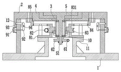
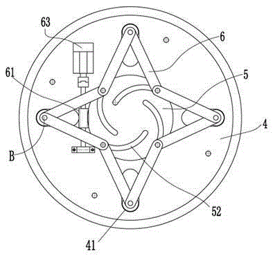
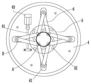
[0016] reference figure 1 and image 3 , This embodiment discloses an automatic workpiece clamping device, including a connecting base 1, a worktable turntable 2, a spindle sleeve 3, an automatic centering flower disk 4, a parabolic flower disk 5, 8 connecting rods 6 and 4 positioning claws (in the figure) (Not shown), the worktable turntable 2 is rotatably arranged above the connecting base 1 through a worktable rotating mechanism to locate the required processing position. The outer disk must be locked when processing parts, and the spindle The sleeve 3 is fixed under the middle of the worktable turntable 2. The parabolic faceplate 5 is rotatably arranged on the worktable turntable 2. A faceplate drive shaft 51 is connected below the parabolic faceplate 5, and the faceplate drive shaft 51 extends The lower part of the main shaft sleeve 3 is in transmission conn...


PUM


Abstract

The invention provides a workpiece automatic clamping device, which is convenient to operate, and the workpiece automatic centering function is realized. The workpiece automatic clamping device comprises a connecting base, a worktable turntable, a main shaft sleeve, an automatic centering disc chuck, a parabolic disc chuck, a plurality of connecting rods and a plurality of positioning claws, wherein the worktable turntable is rotationally arranged above the connecting base; the main shaft sleeve is fixedly arranged below the worktable turntable; the parabolic disc chuck is rotationally arranged on the worktable turntable; the automatic centering disc chuck is fixedly arranged on the worktable turntable; the parabolic disc chuck is provided with arc-shaped involute grooves from the inside to the outside in the radial direction; the connecting rods are hinged to each other end to end; two ends of each connecting rod are respectively a first hinge end and a second hinge end; the first hinge ends are respectively hinged to the involute grooves on the parabolic disc chuck; the automatic centering disc chuck is uniformly provided with long hinge grooves corresponding to the arc-shaped involute grooves in quantity; the second hinge ends are respectively hinged to the long hinge grooves; the positioning claws are respectively arranged above the connected first hinge ends.

Description

Technical field [0001] The invention relates to machining equipment, in particular to a workpiece automatic clamping device. Background technique [0002] When drilling holes on the plane of flange and tube sheet parts, it is necessary to fix the flange and tube sheet parts on the workbench, and determine the drilling datum of flange and tube sheet parts, and then perform the drilling. At present, in the drilling production of CNC plane drilling machines, a number of T-slots are usually arranged on the bed, the workpiece is fixed by means of pressing the flat plate with tooling, and the center of the workpiece is determined by the photoelectric edge finder as the drilling benchmark. The clamping position of the workpiece to be processed is different, which leads to the different machining datum position during processing. The photoelectric edge finder must be used to determine the machining datum of the workpiece before each processing. The automatic centering function of the wor...

Claims


Application Information

Patent Timeline
Patent Type & Authority Patents(China)
IPC IPC(8): B23Q3/08
CPCB23Q3/08B23Q2703/04
Inventor 甘木林
Owner 南通棉锦纺织品有限公司
Why Eureka
Try Eureka