Self-centering clamping device of drill press workpiece

A clamping device and self-centering technology, which is applied in the direction of positioning device, clamping device, feeding device, etc., can solve the problems of different processing reference positions, reduce the processing efficiency of drilling machine, troublesome operation, etc., and achieve simple operation and shorten processing preparation Time, the effect of improving processing efficiency

Active Publication Date: 2014-05-21
HUHANG TECH GRP CO LTD
View PDF5 Cites 38 Cited by
  • Summary
  • Abstract
  • Description
  • Claims
  • Application Information

AI Technical Summary

Problems solved by technology

At present, in the drilling production of CNC plane drilling machines, a number of T-shaped slots are usually arranged on the bed, and the workpiece is fixed by pressing the flat plate with the tooling, and the center of the workpiece circle is determined by the photoelectric edge finder as the drilling datum. The clamping positions of the workpieces to be processed are different, resulting in different machining reference positions during processing. Before each processing, it is necessary to use a photoelectric edge finder to determine the processing reference of the workpiece. The automatic centering function of the workpiece cannot be realized, and the center of the workpiece cannot be aligned with the The center of the processing table is automatically matched, the operation is troublesome, and the processing preparation time is long, which greatly reduces the processing efficiency of the drilling machine

Method used


Image

  • Self-centering clamping device of drill press workpiece
  • Self-centering clamping device of drill press workpiece
  • Self-centering clamping device of drill press workpiece

Examples


Embodiment Construction

[0015] The present invention will be further described in conjunction with the accompanying drawings and specific embodiments.

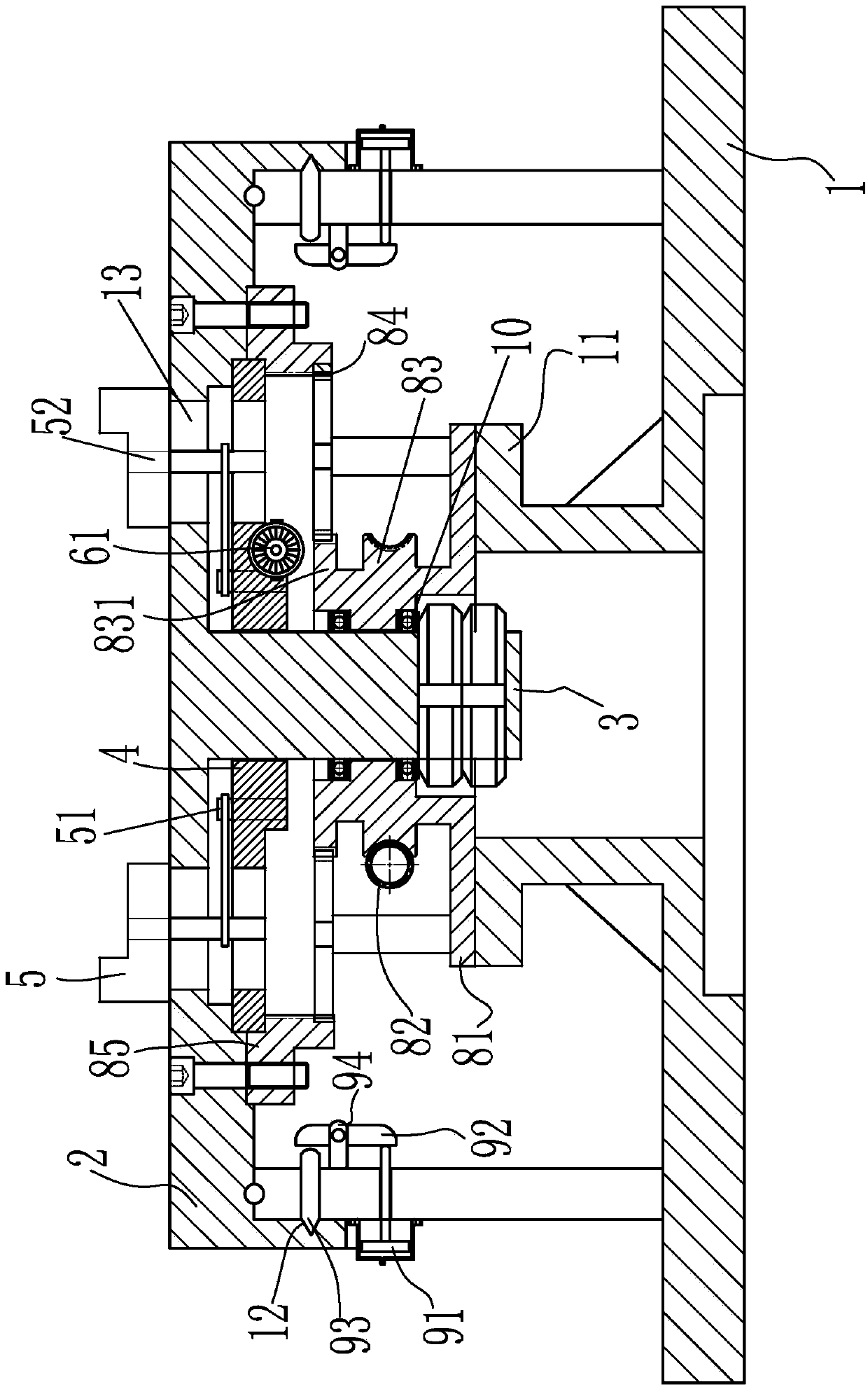
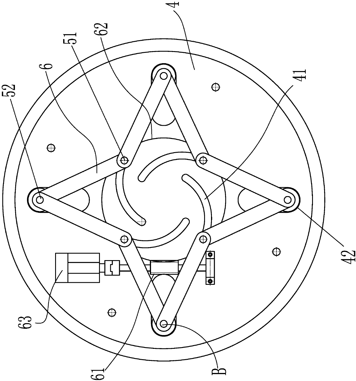
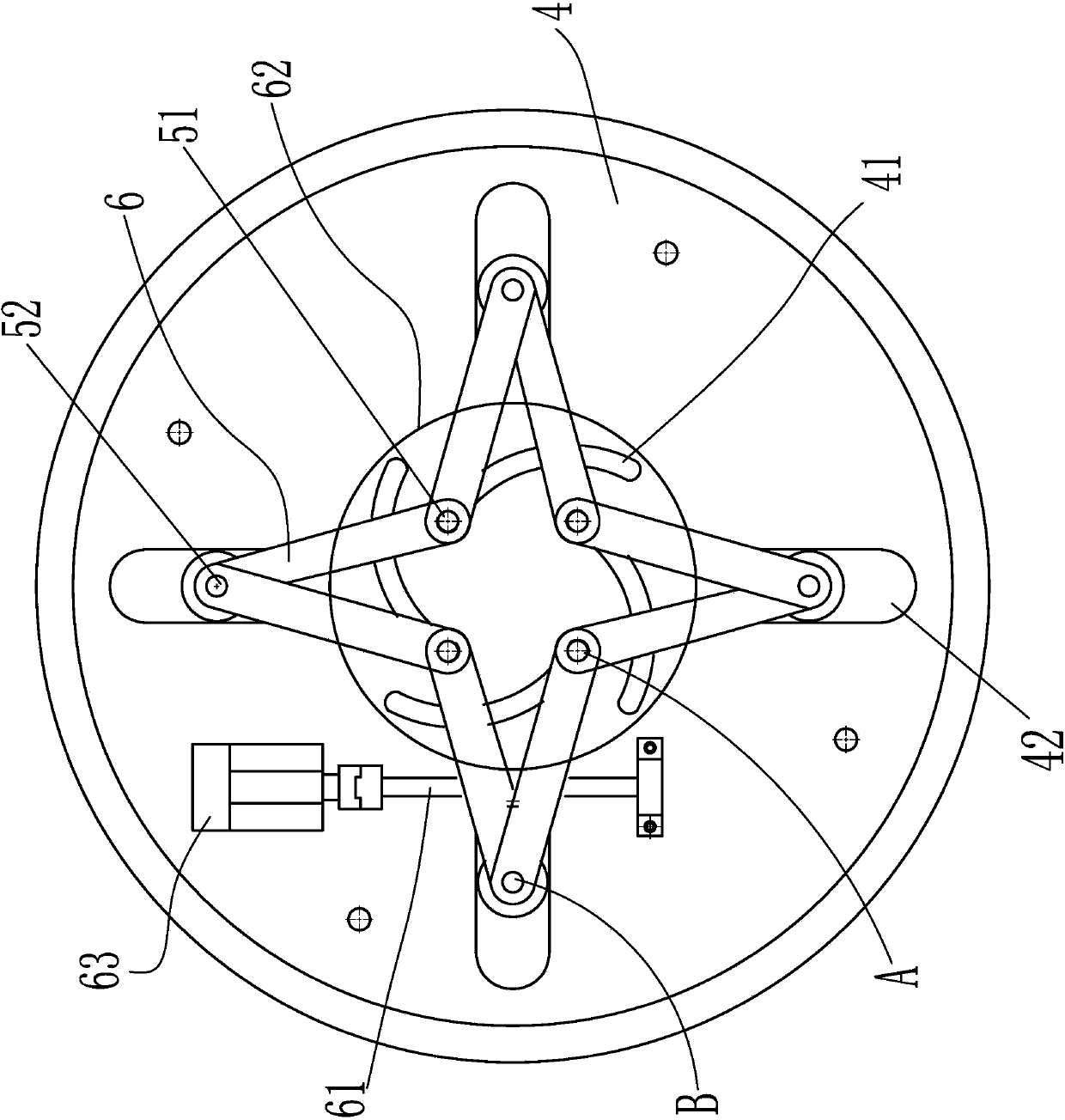
[0016] refer to figure 1 and image 3 , this embodiment discloses a self-centering clamping device for drilling machine workpieces, including a connecting base 1, a worktable turntable 2, a main shaft 3, a parabolic self-centering faceplate 4, a plurality of connecting rods 6 and a plurality of positioning claws 5, the workbench The turntable 2 is rotatably arranged on the top of the connecting base 1 through the workbench rotating mechanism, so as to locate the required processing position. When processing parts, the workbench turntable must be locked, and the spindle 3 is fixed on the workbench turntable. Below the middle of 2, the parabolic self-centering faceplate 4 is rotatably arranged below the worktable turntable 2 on the main shaft 3 through a transmission mechanism. The transmission mechanism includes a worm 61 and a faceplate drive motor ...


PUM


Abstract

The invention provides a self-centering clamping device of a drill press workpiece. The device can realize the self-centering function for a workpiece. The device comprises a connecting base, a workbench rotary disc, a main shaft, a parabola self-centering flower disc, a plurality of connecting rods and a plurality of positioning pawls, wherein the workbench rotary disc can be arranged above the connecting base in a rotary way, the main shaft is fixedly arranged below the middle part of the workbench rotary disc, the parabola self-centering flower disc can be arranged below the workbench rotary disc on the main shaft by a transmission mechanism in a rotary way, arc-shaped gradually slotting grooves are uniformly formed in the parabola self-centering flower disc in the radial direction, the head of one connecting rod is hinged to the end of the other connecting rod, both ends of each of the connecting rods are respectively a first hinging end and a second hinging end, the first hinging ends are respectively hinged to the arc-shaped gradually slotting grooves on the parabola self-centering flower disc, long hinging grooves corresponding to the positions of the peripheral sides of the arc-shaped gradually slotting grooves are respectively formed in the parabola self-centering flower disc, the second hinging ends are respectively hinged to the long hinging grooves in a hinge way, and the positioning pawls are respectively arranged above the second hinging ends of the connecting rods.

Description

technical field [0001] The invention relates to machining equipment, in particular to a self-centering clamping device for drilling machine workpieces. Background technique [0002] When drilling holes on the plane of flanges and tube-sheet parts, it is necessary to fix the flanges and tube-sheet parts on the workbench, and determine the drilling datum of flanges and tube-sheet parts before drilling. At present, in the drilling production of CNC plane drilling machines, a number of T-shaped slots are usually arranged on the bed, and the workpiece is fixed by pressing the flat plate with the tooling, and the center of the workpiece circle is determined by the photoelectric edge finder as the drilling datum. The clamping positions of the workpieces to be processed are different, resulting in different machining reference positions during processing. Before each processing, it is necessary to use a photoelectric edge finder to determine the processing reference of the workpiec...

Claims


Application Information

Patent Timeline
Patent Type & Authority Applications(China)
IPC IPC(8): B23Q3/06
CPCB23Q1/28B23Q1/30B23Q3/06B23Q3/183B23Q5/48B23Q2703/02B23Q2705/14
Inventor 陈文恭陈润福彭建清魏永端郑开省
Owner HUHANG TECH GRP CO LTD
Why Eureka
Try Eureka