Winder Workstation

A workstation and winding machine technology, applied in the direction of thin material processing, conveying filamentous materials, transportation and packaging, etc., can solve the problems of large wire tension peak, limit the speed of wire removal, and change of wire removal speed, etc., to achieve Efficiency improvement, removal speed improvement, quality improvement effect

Inactive Publication Date: 2017-01-11
SAURER GERMANY GMBH & CO KG
View PDF7 Cites 0 Cited by
  • Summary
  • Abstract
  • Description
  • Claims
  • Application Information

AI Technical Summary

Problems solved by technology

[0007] Although it is possible to limit or reduce the thread tension (which increases continuously during the tube stroke) without corresponding measures by these known devices, it is not possible to eliminate other disadvantageous physical factors, namely During the winding process, the thread removal speed has a large change
This large variation in the wire take-off speed due to the traversing of the wire while winding the cross-wound bobbin leads to considerable wire tension peaks during rewinding, which greatly limits what can be achieved in practice. thread removal speed

Method used


Image

  • Winder Workstation
  • Winder Workstation
  • Winder Workstation

Examples


Embodiment Construction

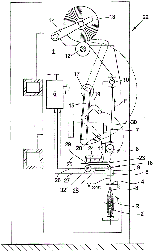
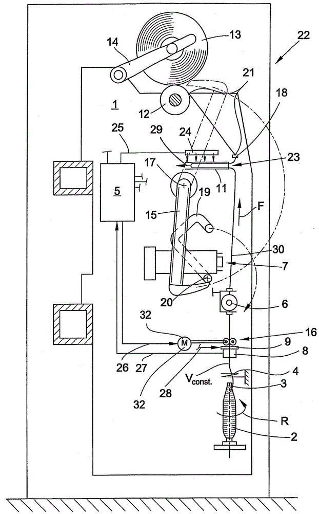
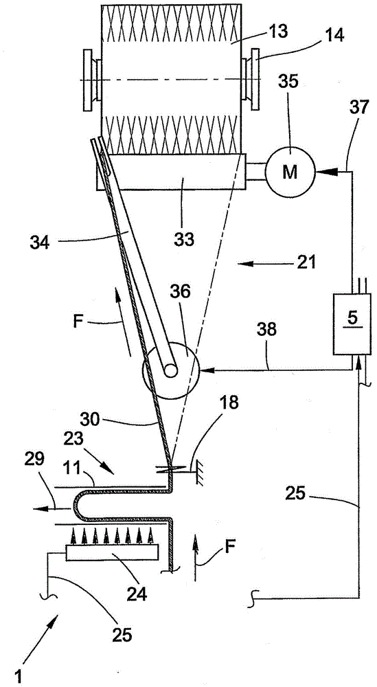
[0039] figure 1 , figure 2 and Figure 4 , Figure 5 Each of the workstations 1 of the automatic crosswinder 22 is shown schematically in side view. Such an automatic crosswinder 22 has a plurality of workstations 1 arranged side by side in a row between their end frames (not shown). Feed bobbins (usually spinning bobbins 2 ), produced for example on a ring spinning machine (not shown), are rewound at these stations or winders 1 to form high-capacity cross-wound bobbins 13 . For this purpose, the workstation 1 is equipped with various processing devices and thread inspection devices, which can be actuated in a defined manner respectively by the control device of the workstation itself, the so-called winder computer 5 . In other words, the workstation 1 has a winding device for producing cross-wound bobbins 13, a device 7 for pneumatically connecting thread ends after thread breakage or yarn clearer cutting, or other thread handling devices.

[0040] The winding device ha...


PUM


Abstract

The invention relates to a working spot of a winding frame, comprising a creel for rotatably supporting a cross-wound bobbin, a device for rotating the cross-wound bobbin, a thread guide for traversing and a thread take-off device which removes a thread from a spinning cop. According to the invention, the thread take-off device (16) removes the thread (30) from the spinning cop (2) at a take-off speed (Vconst.) which is independent of any deviations caused by the traversing. A thread storage (23) is disposed downstream of the thread take-off device (16), when seen in the direction of threadline, and is adapted to the changing thread requirement caused by the traversing of the thread (30).

Description

[0001] This application is a divisional application of the invention patent application with the filing date: October 22, 2005, the application number: 200580040793.9 (the international application number: PCT / EP2005 / 011369), and the invention name is "winding machine workstation". technical field [0002] The invention relates to a winding machine workstation. Background technique [0003] Feed bobbins (preferably spinning bobbins produced on ring spinning machines) containing smaller amounts of yarn are rewound on the stations of such winders to form high-capacity cross-wound bobbins. During rewinding, the yarn is also monitored for yarn defects, which are cut off and replaced by thread splices that look identical to the yarn. [0004] In this case, the winding speed in operation of such so-called automatic cross-winders is generally limited to less than 2000 m / min due to various physical factors, in particular due to the thread tension generated during the rewinding proce...

Claims


Application Information

Patent Timeline
Patent Type & Authority Patents(China)
IPC IPC(8): B65H59/10B65H59/38B65H57/00
CPCB65H51/20B65H51/205B65H59/387B65H59/388B65H2701/31
Inventor 莫尼克·格里希-莱费尔德吉多·施皮克斯贝恩德·勒尔施沃尔夫·迈克尔·鲁
Owner SAURER GERMANY GMBH & CO KG
Why Eureka
Try Eureka