Rotary punching machine

A stamping machine and rotary technology, which is applied in the field of stamping machines, can solve problems such as crushing of workers' hands, unsuitability for mass production, and inability to place and place workpieces and stamping actions at the same time, so as to improve stamping efficiency and speed up Effect

Inactive Publication Date: 2022-01-25
沈瑜
View PDF0 Cites 0 Cited by
  • Summary
  • Abstract
  • Description
  • Claims
  • Application Information

AI Technical Summary

Problems solved by technology

[0002] The current stamping machines are generally single-mold direct-acting stamping. After a stamping action is completed, the finished product needs to be removed manually, and then the unstamped workpiece is placed on the mold for stamping. In the process of frequent pick-and-place workpieces, If there is a little carelessness, the worker's hands may be crushed by the machine tool, there is a greater risk, and the placement of the workpiece and the stamping action cannot be carried out at the same time, which leads to the low processing efficiency of ordinary stamping machine tools, which is not suitable for large quantities Production

Method used


Image

  • Rotary punching machine
  • Rotary punching machine
  • Rotary punching machine

Examples


Embodiment Construction

[0022] In order to make the objects and advantages of the present invention clearer, the present invention will be described in detail below in conjunction with the examples. It should be understood that the following words are only used to describe one or several specific implementation modes of the present invention, and do not specifically request the present invention. The scope of protection is strictly defined. As used herein, the terms up and down and side to side are not limited to their strict geometric definitions, but include reasonable and inconsistent tolerances for machining or human error. This kind of rotation is described in detail below The specific characteristics of the stamping machine:

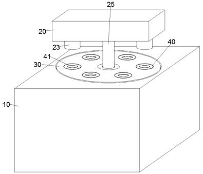
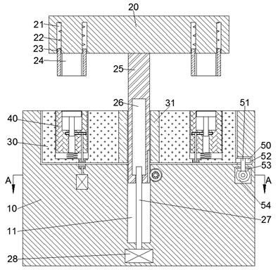
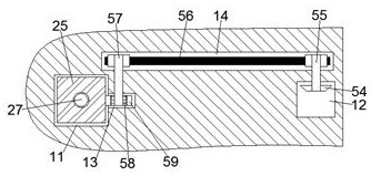
[0023] refer to Figure 1-Figure 5 , a rotary punching machine according to an embodiment of the present invention, comprising a punching table 10, a rotating mechanism is arranged inside the punching table 10, and a punching mechanism is arranged on the upper side of the...


PUM


Abstract

The invention discloses a rotary punching machine which comprises a punching table, a rotating mechanism is arranged in the punching table, and a punching mechanism is arranged on the upper side of the punching table. Through up-down reciprocating motion of a lifting rod, a driven gear can be driven to rotate forward and backward in a reciprocating manner, and a rotating disc is driven to rotate intermittently through a one-way bearing, so that a die intermittently rotates with the lifting rod as the center and is matched with vertical movement of a punching block, continuous punching of workpieces is achieved, a worker can place the workpieces on the die on the front side of a punching base before punching operation of the punching block, and the risk that the hands are injured during punching is avoided; and meanwhile, an ejection block moving up and down is matched in the punching process, the workpiece can be ejected out after punching is completed, the speed of taking down the workpiece from the die is increased, and the punching efficiency is improved.

Description

technical field [0001] The invention relates to the related technical field of punching machines, in particular to a rotary punching machine. Background technique [0002] The current stamping machines are generally single-mold direct-acting stamping. After a stamping action is completed, the finished product needs to be removed manually, and then the unstamped workpiece is placed on the mold for stamping. In the process of frequent pick-and-place workpieces, If there is a little carelessness, the worker's hands may be crushed by the machine tool, there is a greater risk, and the placement of the workpiece and the stamping action cannot be carried out at the same time, which leads to the low processing efficiency of ordinary stamping machine tools, which is not suitable for large quantities Production. Contents of the invention [0003] The object of the present invention is to provide a rotary punching machine for overcoming the above-mentioned defects in the prior art. ...

Claims


Application Information

Patent Timeline
IPC IPC(8): B21D37/14B21D45/04B21D55/00
CPCB21D37/14B21D45/04B21D55/00
Inventor 潘丽芳
Owner 沈瑜
Why Eureka
Try Eureka