Inner tub structure for washing machines

A washing machine and inner tub technology, applied in the field of washing machines, can solve problems such as unbalance, waste of energy, affecting the service life of the washing machine, etc., and achieve the effect of prolonging the service life and avoiding drumming or imbalance.

Inactive Publication Date: 2014-05-28
慈溪市可意电器有限公司
View PDF1 Cites 0 Cited by
  • Summary
  • Abstract
  • Description
  • Claims
  • Application Information

AI Technical Summary

Problems solved by technology

[0003] However, when the washing machine in the prior art is washing and dehydrating, the conversion between the clockwise rotation of the pulsator and the counterclockwise rotation of the pulsator and the inner tub is achieved through the action of the clutch device and the belt, so the structure is complicated and the motor bears The load is large, which wastes energy. In addition, during the dehydration process, since the motor drives the inner tub to rotate, the pulsator rotates with it, and the inner tub of the washing machine will be drummed or unbalanced with the outer tub or base, which will affect the use of the washing machine. life

Method used


Image

  • Inner tub structure for washing machines
  • Inner tub structure for washing machines

Examples


Embodiment 1

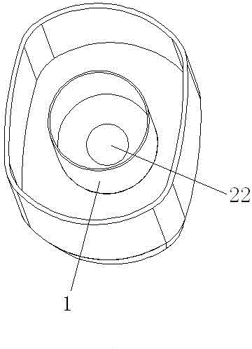
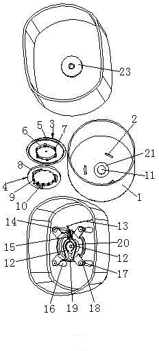
[0032] Such as figure 1 with figure 2 As shown, an inner tub structure of a washing machine includes an inner tub 1. The inner bottom of the inner tub 1 is provided with a buckle groove 2, and the buckle groove 2 is matched with a pulsator device, and the pulsator device includes an inner bottom connected to the inner tub 1. The wave blocking rotating plate 3 is provided with a collar 4 between the wave blocking rotating plate 3 and the inner bottom of the inner tub 1. The lower end of the wave blocking wheel device is connected with a locking device; when washing, the wave blocking rotating plate 3 of the present invention Driven by the inner shaft, first rotate clockwise, and then rotate counterclockwise together with the wave blocking plate 3 through the inner tub 1. This cycle can achieve the effect of washing; during dehydration, the inner barrel 1 rotates with the wave blocking plate 3, and finally To achieve the effect of dehydration, the lower end of the locking device ...

Embodiment 2

[0036] The difference between this embodiment and the first embodiment is that the dynamic balancing device includes a support column 16 arranged at the bottom of the base, the upper end of the support column 16 is provided with a second spring 17, and the upper end of the second spring 17 is provided with a sleeve column 18, The upper end of the sleeve column 18 is provided with a dynamic balance bracket 19, the locking clip 12 is provided at the upper end of the dynamic balance bracket 19, and the lower end of the dynamic balance bracket 19 is provided with a motor 20. The motor 20 is screwed to the inner shaft through a connecting sleeve. A shaft sleeve is provided between the connecting sleeve and the bottom of the base. At least three support columns 16 are provided at the bottom of the base. The upper ends of the three support columns 16 are provided with second springs 17, and the upper ends of each second spring 17 are provided with The sleeve column 18, in this embodime...


PUM


Abstract

The invention relates to the technical field of washing machines, in particular to an inner tub structure for washing machines. The inner tub structure comprises an inner tub; the inner bottom of the inner tub is provided with fastening grooves; a pulsator retainer is fitted to the fastening grooves and comprises a pulsator retaining rotary plate connected to the inner bottom of the inner tub; a ring is arranged between the pulsator retaining rotary plate and the inner bottom of the inner tub; a locking device is connected to the lower end of the pulsator retainer through a shaft; a base is arranged below the locking device; a dynamic balance device is arranged between the base and the locking device. During washing, the pulsator retaining rotary plate is driven by an inner shaft to rotate clockwise, and then the inner tub rotates anticlockwise with the pulsator retaining rotary plate; as the cycle goes on, washing is achieved. During dewatering, the inner rotates with the pulsator retaining rotary plate so as to achieve dewatering. Through the use of the dynamic balance device used for supporting the inner tub and disposed at the lower end of the locking device, the inner tub of the washing machine is protected from knocking or unbalance, shock is effectively damped and the service life of the washing machine is prolonged.

Description

Technical field [0001] The invention involves the field of washing machine technology and specially involves the inner barrel structure of a washing machine. Background technique [0002] The washing machine uses the motor to rotate the rotary cylinder and the current to achieve its washing process, drift process and dehydration process in turn. It is a kind of stirring on them after putting the washing water and washing lamps into the rotary cylinder.Use the device to be washed between the washing water and the rotary tube. [0003] However, when washing machines in existing technologies, when washing and dehydration, the tide rotation of the pulsator of the pulsator and the overall rotation of the pulsator and the inner barrel overall clockwise rotating was achieved through the action of clutch device and belt.Large loads and waste of energy. In addition, during the dehydration process, because the motor drives the inner barrel rotation, the pulsator rotates with one.life. Inv...

Claims


Application Information

Patent Timeline
Patent Type & Authority Applications(China)
IPC IPC(8): D06F37/02D06F37/20D06F37/40D06F37/00
CPCD06F37/02D06F37/20D06F37/40
Inventor 梁谦发
Owner 慈溪市可意电器有限公司
Why Eureka
Try Eureka