Optical scanner and image forming apparatus

a technology of optical scanners and forming apparatuses, applied in the field of optical scanners and image forming apparatuses, can solve the problems of inability to turn the inside movable plate about the x axis and the y axis under the same conditions, inability to turn the inside movable plate about the x axis and the y axis independently, and inability to turn the inside movable plate about the x axis and the y

Active Publication Date: 2012-02-09
SEIKO EPSON CORP
View PDF9 Cites 14 Cited by
  • Summary
  • Abstract
  • Description
  • Claims
  • Application Information

AI Technical Summary

Benefits of technology

[0020]According to the image forming apparatus of this application example, it is possible to perform turning of the movable section about one of two axes which are at right angles to each other and turning of the movable section about the other axis independently. This makes it possible to turn the movable section about two axes which are at right angles to each other with stability.

Problems solved by technology

This makes it impossible to turn the inside movable plate about the X axis and the Y axis under the same conditions.
In addition, in the actuator of Patent Document 1, the magnetic field generated from the coil provided in the outside movable plate and the magnetic field generated from the coil provided in the inside movable plate interfere with each other, making it impossible to turn the inside movable plate about the X axis and the Y axis independently.
Thus, the actuator of Patent Document 1 has a problem that it is impossible to turn the inside movable plate about the X axis and the Y axis with stability.

Method used


Image

  • Optical scanner and image forming apparatus
  • Optical scanner and image forming apparatus
  • Optical scanner and image forming apparatus

Examples


first embodiment

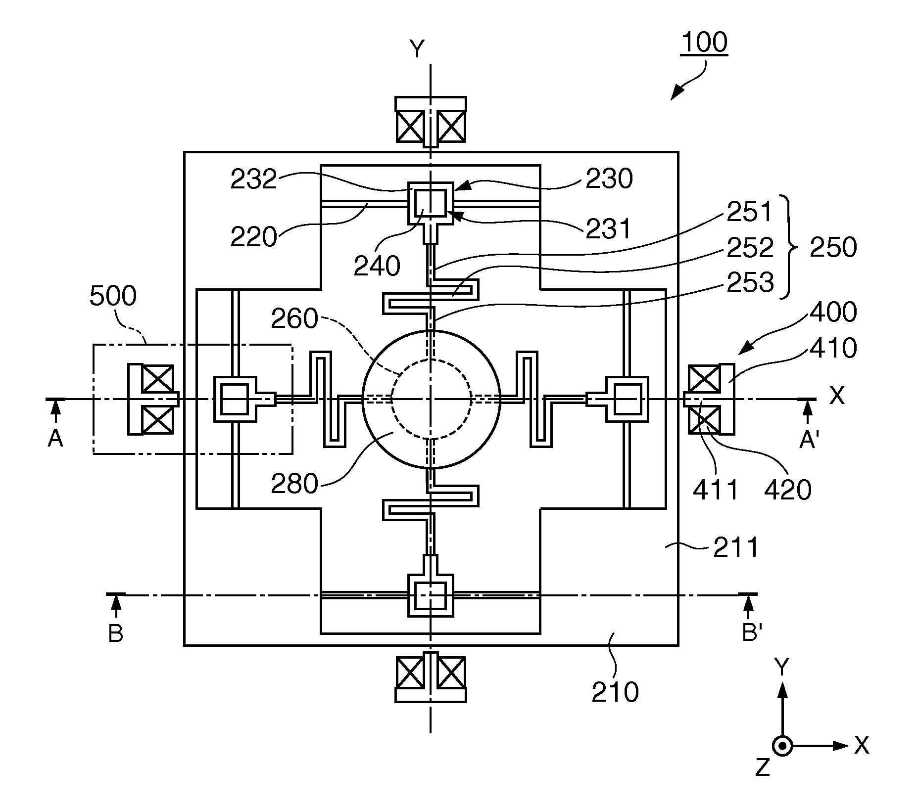
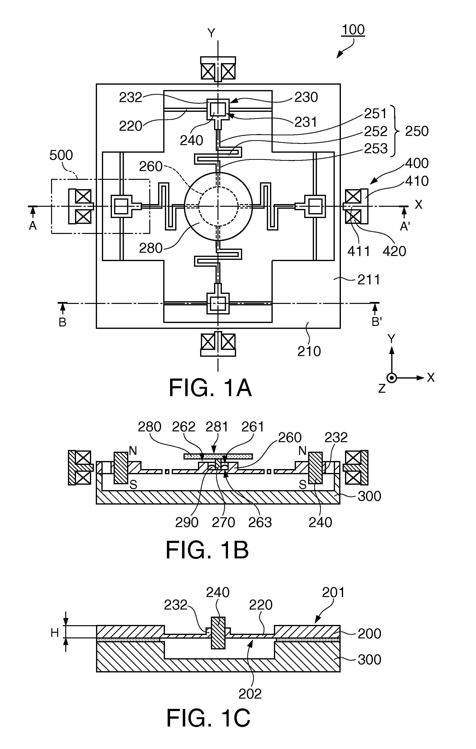
[0031]FIGS. 1A to 1C show an optical scanner of a first embodiment, FIG. 1A is a plan view, FIG. 1B is a sectional view taken on the line A-A′ of FIG. 1A, and FIG. 1C is a sectional view taken on the line B-B′ of FIG. 1A. As shown in FIG. 1C, an optical scanner 100 shown in FIG. 1A includes a vibrating substrate 200, a pedestal 300, and driving sections 400 relatively fixed, by unillustrated means, to the vibrating substrate 200 fixed to the pedestal 300.

[0032]The vibrating substrate 200 includes, in the outer periphery thereof, a supporting frame 210 formed into a frame having a substantially rectangular shape. At the four corners of the supporting frame 210, fixed sections 211 fixed to the pedestal 300 by means of bonding are provided. Moreover, from each fixed section 211, drive beams 220 extend in parallel to illustrated X- and Y-axis directions and each connect to a corresponding one of displacement sections 230 provided in portions in which the directions in which the drive be...

second embodiment

[0058]Moreover, by using a two-layered vibrating substrate 600 of a second embodiment shown in FIG. 6, it is possible to implement the invention easily. FIG. 6 is a sectional view showing the outline of an optical scanner 110 according to the second embodiment, in which the vibrating substrate 200 of the optical scanner 100 according to the first embodiment described above is replaced with a two-layer structure formed of a first vibrating substrate 610 and a second vibrating substrate 620. Both the first vibrating substrate 610 and the second vibrating substrate 620 are formed of a silicon substrate and bonded together by a silicon oxide film 630 to form a two-layer structure. Incidentally, the planar shape of the optical scanner 110 is the same as that of the optical scanner 100 according to the first embodiment described above.

[0059]The first vibrating substrate 610 includes a displacement section 640 provided with a bar-like permanent magnet 240, a movable beam 650 which extends ...

third embodiment

[0062]An image forming apparatus using the optical scanner 100 according to the first embodiment described above and the optical scanner 110 according to the second embodiment described above will be described. In this embodiment, a projector is illustrated as an example; however, the invention can also be suitably applied to an image forming apparatus such as a laser printer, an imaging display, a bar code reader, and a confocal scanning microscope.

[0063]FIG. 7 is a conceptual diagram of a projector 1000 using the optical scanner 100 according to the embodiment described above. Incidentally, for convenience of explanation, a longitudinal direction of a screen 1400 is referred to as a “lateral direction” and a direction perpendicular to the longitudinal direction is referred to as a “vertical direction”.

[0064]The projector 1000 has a light source device 1100 emitting a light such as a laser, a plurality of dichroic mirrors 1200, and the optical scanner 100. The light source device 1...


PUM


Abstract

An optical scanner includes: a light reflecting section having a light reflecting surface; a supporting section supporting the light reflecting section; a movable section supporting the supporting section; at least a pair of movable beams extending from the movable section and disposed in such a way that the movable beams face each other; a displacement section connected to the movable beam; two drive beams each extending from the displacement section; and a supporting frame supporting the drive beams, wherein the movable beams each include a bending section which is bent and deformed in a thickness direction of the supporting frame, and an end on the side of the movable section of the supporting section is fixed in a position more distant from the light reflecting section than an end face on the side of the light reflecting section of the movable section.

Description

BACKGROUND[0001]1. Technical Field[0002]The present invention relates to optical scanners and image forming apparatuses.[0003]2. Related Art[0004]For example, as an optical scanner for performing drawing by optical scanning in a laser printer or the like, an optical scanner which is formed of a torsion oscillator and uses an actuator has been known (see, for example, JP-A-2005-181395 (Patent Document 1)).[0005]In Patent Document 1, an actuator having an insulating substrate in which a pair of permanent magnets is provided and a scanner main body supported by the insulating substrate so as to be located between the pair of permanent magnets is disclosed. Moreover, the scanner main body has a frame-shaped supporting section, a frame-shaped outside movable plate provided inside the supporting section, and an inside movable plate (mirror) provided inside the outside movable plate. Furthermore, the outside movable plate is connected to a supporting section via a pair of first torsion bar...

Claims


Application Information

Patent Timeline
Patent Type & Authority Applications(United States)
IPC IPC(8): G02B26/10
CPCG02B26/101G02B26/085
Inventor MIZOGUCHI, YASUSHIMIYAMOTO, YUKIO
Owner SEIKO EPSON CORP
Why Eureka
Try Eureka