Projection objective

a technology of projection objective and projection lens, applied in the field of projection objective, can solve the problem of substantially worse reproduction quality

Inactive Publication Date: 2003-06-19
BCI FINANZ +1
View PDF1 Cites 15 Cited by
  • Summary
  • Abstract
  • Description
  • Claims
  • Application Information

AI Technical Summary

Benefits of technology

0003] The purpose of the invention is an objective, respectively a series of objectives, which on one hand guarantees the most effective use of luminous flux diffusion throughout an enti...

Problems solved by technology

Also, reproduction quality is sub...

Method used


Image

  • Projection objective
  • Projection objective
  • Projection objective

Examples


Embodiment Construction

[0014] Preliminary Remark:

[0015] For practical reasons, the sectional views, flux progressions and evaluation of reproduction quality in the following illustrations refer to a reversed position opposite the projection objective's position of use (reproduction from enlarged to shrunk side.) The entrance's intersection width s=infinite. Therefore the original object is inevitably turned toward the image and reversed. This reversal is referenced colloquially. An exception to this is pupil reproduction (orientation in position of use). This should be noted in the following explanations.

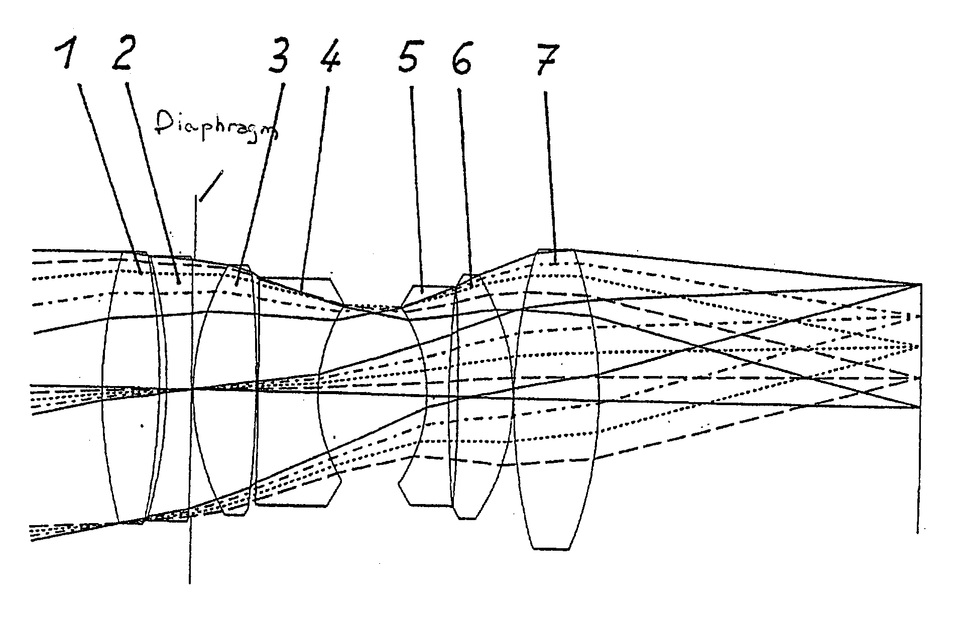
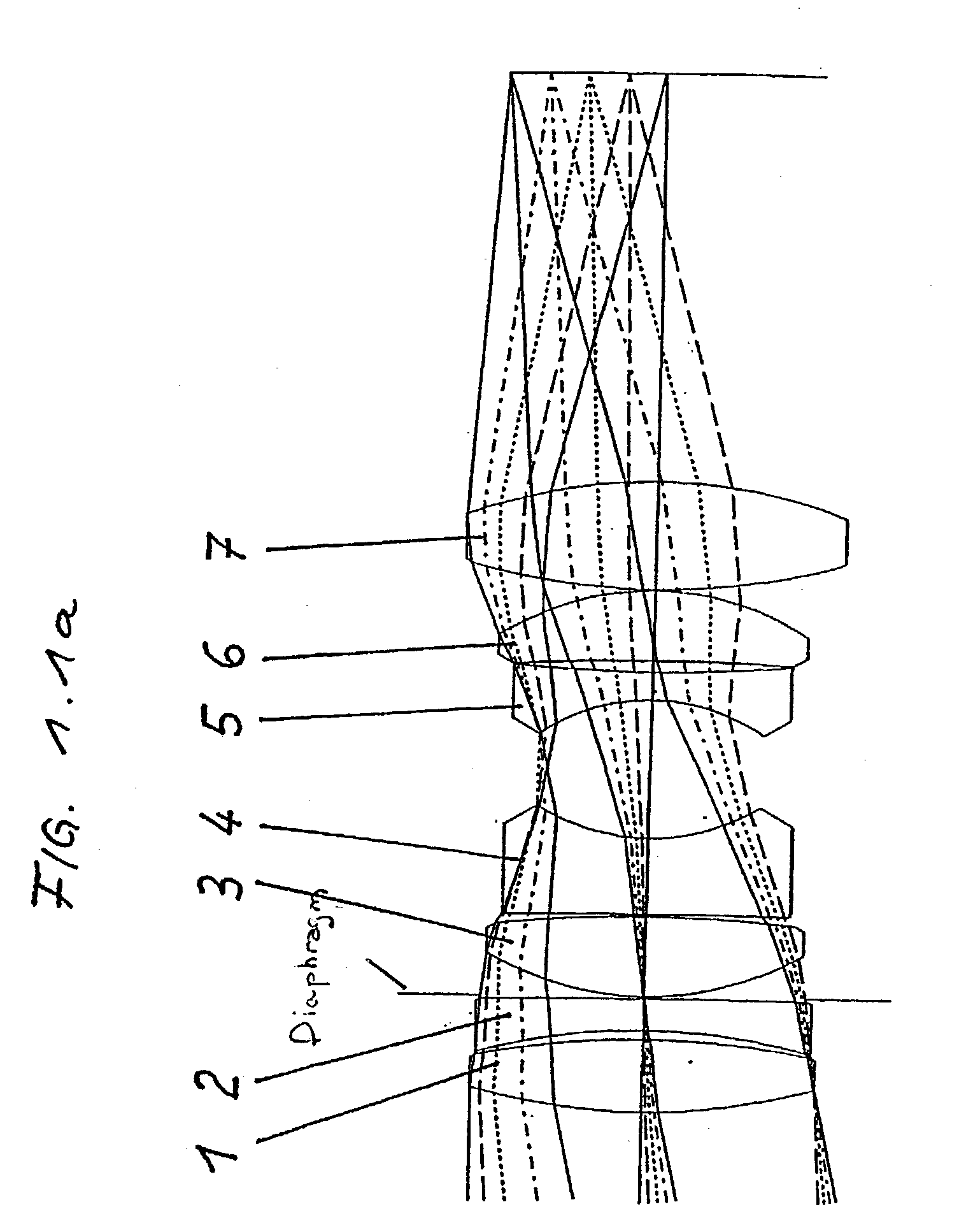
[0016] The following illustrations exhibit the luminous projection objective with a curved image area according to claim 3:

[0017] 1.1a System's sectional view with numbered lenses and flux progression on the meridional level for the reproduction of different object points. The diaphragm is located between lenses 2 and 3.

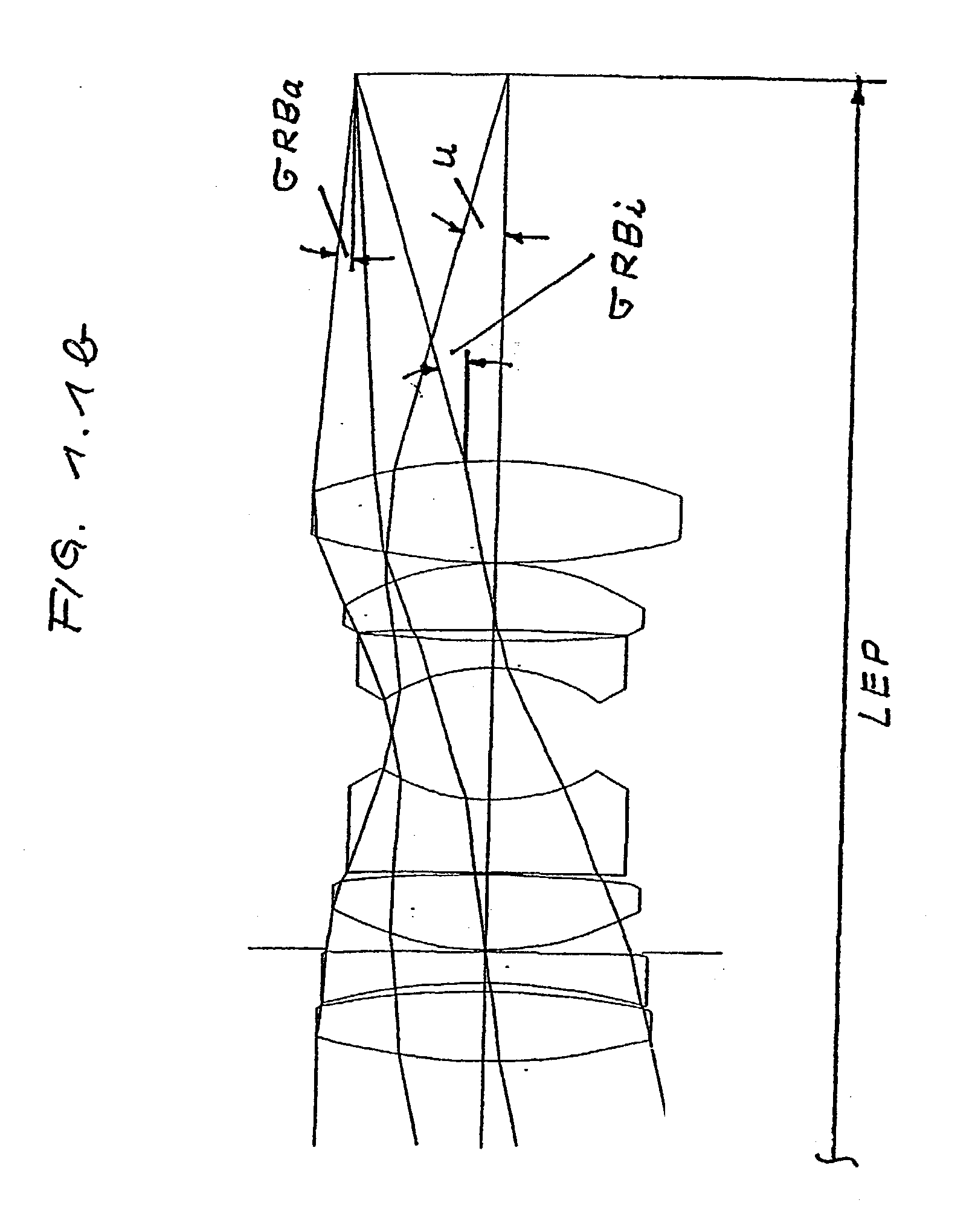
[0018] 1.1b System's sectional view with flux progression on the meridional level for ...


PUM


Abstract

The invention relates to a projection objective which consists of at least seven lenses that are adjacent to air on both sides. The inventive projection objective meets the criteria of the following equations in its totality: u>=12.8°; 100 mm<=LEP<=400 mm; sigmaRBa>=1°; sigmaRBi<=-14°, whereby u is the aperture angle (2u-entire angle) on the illumination side; LEP is the distance from the entrance pupil (on the illumination side) to the object level (the position in the direction of projection from the reference point: object level corresponds to a positive value); sigmaRBa is the angle inclination of the beam in relation to the optical axis in the object space between the object and the 1. lens surface of the objective, said beam limiting the bundle for the field edge (outer field point in the object) towards the outside (away from the optical axis, far from the axis) and sigmaRBi is the angle inclination of the beam in relation to the optical axis in the object space between the object and the 1. lens surface of the objective, said beam limiting the bundle for the field edge (outer field point in the object) towards the inside (towards the optical axis, close to the axis). The angles sigmaRBa and sigmaRBi are positive when the corresponding beams intersect the optical axis in a point which is situated in the opposite direction of projection when seen from the object. Said angles are negative when the beams intersect the optical axis in a point which is situated in the direction of projection when seen from the object.

Description

SCOPE OF THE APPLICATION[0001] The invention's main scope of application is in movie projection, especially with 35 mm film.CHARACTERISTICS OF ESTABLISHED TECHNICAL SOLUTIONS AND GOAL STATEMENT[0002] The invention relates to a luminous projection objective. Known objectives of this type (DE-OS3833946) have been designed for the requirements with projections, whereby the focus is mostly on the grade of reproduction quality. Over many years this has led to a variety of modified Double Gauss objectives (DEOS 3633032, U.S. Pat. No. 4,704,011), which most of all sought to further reduce aberrations. Among other things, one result of this development is that in an advantageous design development, the diaphragm is preferably located in the larger space between the hollow inner surfaces of meniscus-shaped lenses, which is characteristic for Double Gauss objectives. However, this location, though advantageous for the correction of aberrations, exhibits significant disadvantages with projecti...

Claims


Application Information

Patent Timeline
IPC IPC(8): G02B13/02G02B13/00
CPCG02B13/22G02B13/02
Inventor REINECKE, WOLFGANGLINGE, HORST
Owner BCI FINANZ
Why Eureka
Try Eureka