
Model pile foundation with horizontal dynamic loading device

A loading device and horizontal loading technology, which is applied in basic structure engineering, basic structure testing, construction, etc., can solve the problems of inconvenient operation, high construction cost, complicated principle, etc., and achieve the effect of improving similarity

Inactive Publication Date: 2016-08-17
HENAN UNIV OF SCI & TECH
View PDF7 Cites 0 Cited by
  • Summary
  • Abstract
  • Description
  • Claims
  • Application Information

AI Technical Summary

Problems solved by technology

[0003] For the experimental research on the dynamic bearing capacity of pile foundation, it is usually difficult to realize the field test method, and the operation procedure is complicated, and the cost is high, so the research method of indoor test is mostly used
At present, the research on the dynamic characteristics of pile foundations is usually completed in laboratories with large-scale shaking tables, and most of them are input methods of vibration loads in a single direction. This method generally has complicated principles, inconvenient operation, and expensive construction costs.
[0004] In the Chinese journal "Rock and Soil Mechanics", Volume 33, No. 2, "Research on the Horizontal Dynamic Test of Model Pile Foundations under Freezing and Thawing Conditions", a pile dynamic test device is published. The dynamic test device includes a loading frame and a soil box. A soil body is housed in the soil box, and a vertically arranged model pile is inserted in the soil box. A horizontal loading mechanism for applying a horizontal loading force to the model pile is installed on the loading frame. The axis of the horizontal loading mechanism extends along the loading direction. And perpendicular to the axis of the model pile, the horizontal loading mechanism includes the loading shaft, which is used to directly transmit the horizontal vibration load to the model pile. However, this device can only conduct horizontal unidirectional vibration research on the model pile, which is different from the actual working condition. farther away

Method used


Image

  • Model pile foundation with horizontal dynamic loading device
  • Model pile foundation with horizontal dynamic loading device
  • Model pile foundation with horizontal dynamic loading device

Examples


Embodiment Construction

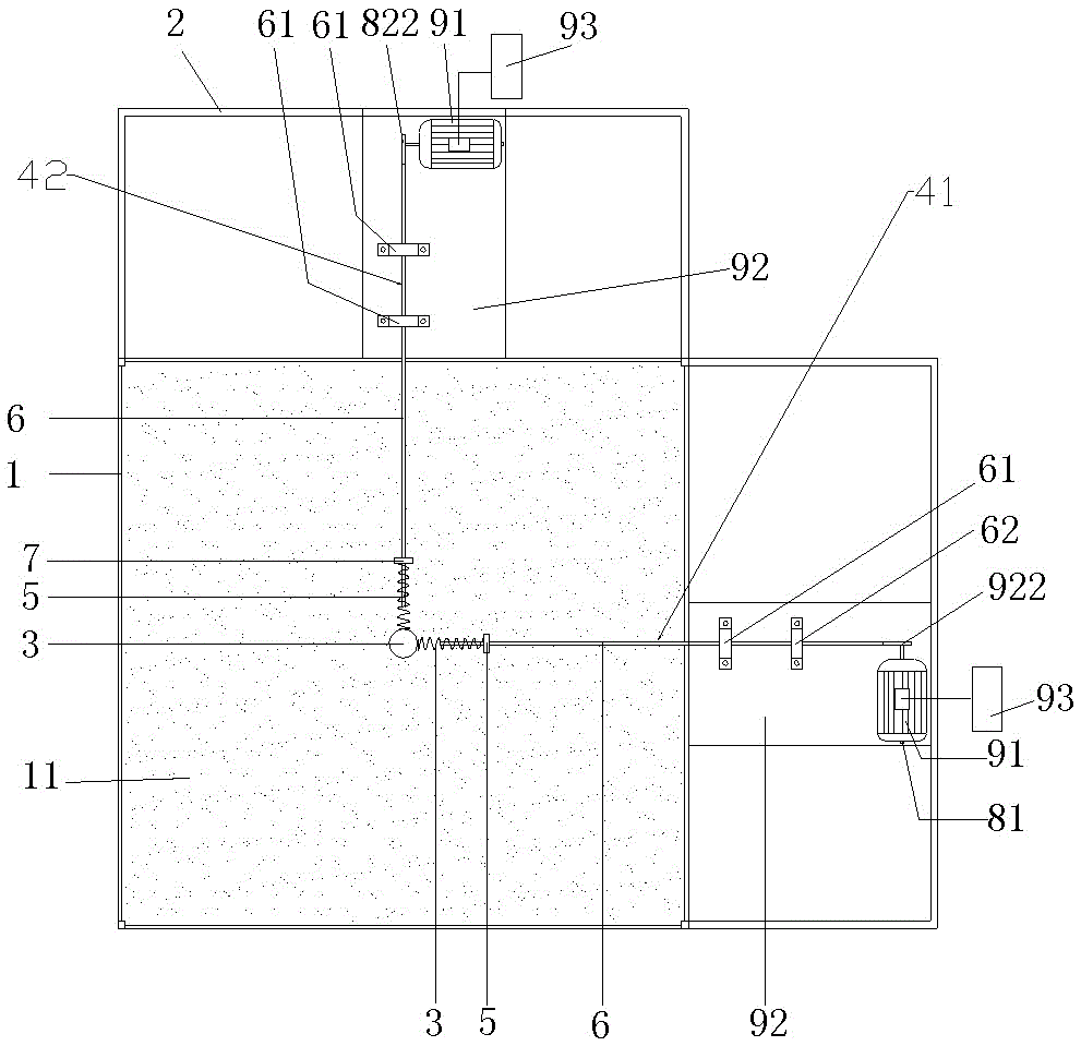
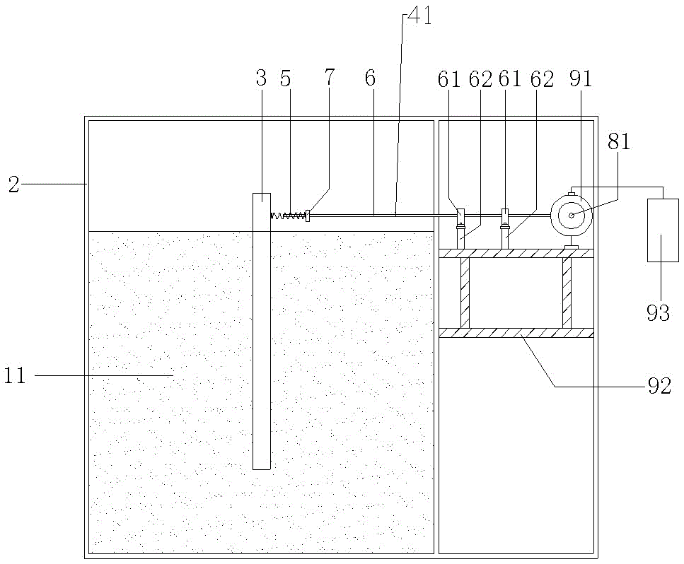
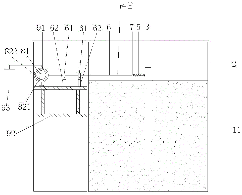
[0031] Embodiment 1 of the model pile foundation with the horizontal dynamic loading device of the present invention, such as Figure 1-8 Shown: the model pile foundation with horizontal dynamic loading device includes soil box 1 , loading frame 2 , model pile 3 and horizontal loading mechanism 4 .

[0032] The soil box 1 has a cube structure, and the soil box 1 is filled with soil body 11 . The model pile 3 extends up and down, the model pile 3 is arranged in the soil box 1, the model pile 3 is located at the center of the soil box 1, the lower part of the model pile 3 is buried in the soil box 1 and is fixed by the soil in the soil box 1, The upper part of the model pile 3 protrudes from the soil body in the soil box 1 . The loading frame is fixed on the outer periphery of the soil box. The loading frame 2 is made of steel. The horizontal loading mechanism 4 is assembled on the loading frame 2 .

[0033] The horizontal loading mechanism 4 is used to apply a horizontal lo...


PUM


Abstract

The invention relates to the technical field of pile foundation simulation devices, in particular to a model pile foundation with horizontal dynamic loading devices. The model pile foundation with the horizontal dynamic loading devices comprises at least two horizontal loading mechanisms. The horizontal loading mechanisms are used for exerting horizontal loading force on a model pile and are provided with axes which extend along loading directions, and the axes of each two adjacent horizontal loading mechanisms are not parallel to each other and are non-collinear. At least two horizontal vibration loads can be inputted to the model pile foundation, so that a load environment of a pile foundation during actual work can be approximately simulated, and a corresponding basis can be provided for research on a dynamic property of the pile foundation under the effect of the horizontal vibration loads. Compared with the prior art, the model pile foundation has the advantage that the pile foundation actual working condition simulation similarity of the model pile foundation can be improved.

Description

technical field [0001] The invention relates to the technical field of pile foundation simulation devices, in particular to a model pile foundation with a horizontal dynamic loading device. Background technique [0002] In terms of the research status of the dynamic characteristics of pile foundations, most of them focus on the vertical bearing capacity, and there are few studies on the bearing capacity under the horizontal vibration load, and they are all studies on horizontal one-way vibration. However, in actual engineering, the pile foundation is often subjected to two-way horizontal vibration loads, such as: the combination of seismic load and water flow load, the combination of earthquake load and wind wave load, the combination of water flow load and vehicle load, and the two mechanical equipment during construction at the same time. Bidirectional vibration loads generated by operation, etc. Therefore, the one-way horizontal vibration study is far from the actual wor...

Claims


Application Information

Patent Timeline
Patent Type & Authority Patents(China)
IPC IPC(8): E02D33/00
Inventor 钟国华高笑娟吕冰李跃辉
Owner HENAN UNIV OF SCI & TECH
Learn More