Simulating device for fluid flow safety evaluation of oil-gas pipelines

A technology for fluid flow and safety evaluation, applied in the direction of measuring devices, instruments, scientific instruments, etc., can solve problems such as insufficient fluid flow safety, drilling platform explosion, environmental pollution, etc., and achieve scientific experimental methods, flexible installation, and comprehensive experimental data collection Effect

Active Publication Date: 2014-03-26
SOUTH CHINA UNIV OF TECH
View PDF8 Cites 41 Cited by
  • Summary
  • Abstract
  • Description
  • Claims
  • Application Information

AI Technical Summary

Problems solved by technology

[0003] The 2010 U.S. Gulf of Mexico crude oil spill was due to the failure of the sealing of the oil pipeline due to the existence of a methane bubble, which eventually caused the "Deepwater Horizon" drilling platform in the Gulf of Mexico to explode and cause a fire, resulting in a series of economic losses and environmental pollution
Scholars from various countries have

Method used


Image

  • Simulating device for fluid flow safety evaluation of oil-gas pipelines
  • Simulating device for fluid flow safety evaluation of oil-gas pipelines
  • Simulating device for fluid flow safety evaluation of oil-gas pipelines

Examples


Example Embodiment

[0035] Example 1

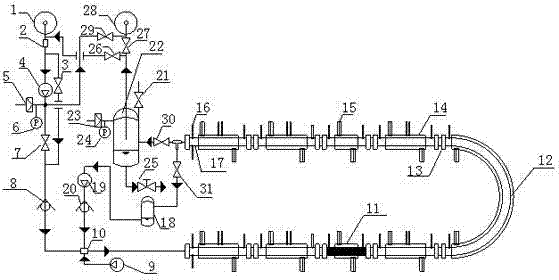
[0036] As attached figure 1 As shown, a simulated oil and gas pipeline fluid flow safety evaluation device includes a multiphase flow circulation system, a separation system, a fluid injection system, and an exhaust gas recovery system.

[0037] The multi-phase flow circulation system includes a gas-liquid mixer 10 connected in turn through auxiliary pipelines to form a circulation loop, a number of detachable pipe sections 17 connected in series by a flange 13, an eighth gate valve 31, a buffer tank 18, and a multi-phase mixed transportation. The pump 19, the second one-way valve 20, the detachable pipe section 17 is also connected with a curved pipe 12 through a flange 13,

[0038] The outer surface of a single detachable pipe section 17 is wrapped with a circulating jacket tube 14. The circulating jacket tube 14 is provided with a refrigerant circulation interface 15 for connecting refrigerant. The two ends of the single detachable pipe section 17 near the flang...

Example Embodiment

[0073] Example 2

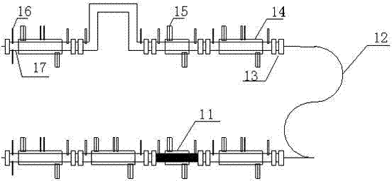
[0074] As attached figure 2 As shown, the difference between this embodiment and the first embodiment is that a part of the detachable pipe section 17 is a straight shape, and a part is a bent shape as shown in the figure, and the curved pipe 12 is an "S" shape.

Example Embodiment

[0075] Example 3

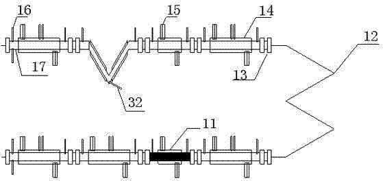
[0076] As attached image 3 As shown, the difference between this embodiment and the first embodiment is that part of the detachable tube section 17 is linear and part is "V" shape, the curved tube 12 is "M" shape, and the 32-focused beam reflects The measuring instrument is installed at the corner of the detachable pipe section 17, which can analyze and measure the flow composition change or particle change of the fluid when the fluid passes through the corner.

[0077]


PUM


Abstract

The invention discloses a simulating device for fluid flow safety evaluation of oil-gas pipelines. The device comprises a multiphase flow circulating system, a separating system, a fluid injecting system and a waste gas recovery system. The device disclosed by the invention emerges on the basis of fully considering the current fluid flow safety hotspot problem and is capable of simulating a low-temperature high-pressure environment to carry out the fluid flow safety evaluation of the oil-gas pipelines, wherein the evaluation content comprises oil-gas pipeline blockage caused by problems such as hydrate and wax deposit and the oil-gas transmission safety problem caused by pipeline corrosion. The device disclosed by the invention is not limited to the evaluation content and can also be used for exploring the research on the evaluation of multi-phase fluid flow regularity, hydrate inhibitor performance and the like. The device disclosed by the invention has the characteristics of reasonable structure, ingenious design, operational flexibility, accuracy in measurement and the like.

Description

Technical field [0001] The invention relates to a safety evaluation device for simulating fluid flow of oil and gas pipelines. It belongs to the technical field of oil and gas pipeline fluid flow safety guarantee. Background technique [0002] In oil and gas pipelines, pipeline blockages caused by problems such as hydrates and wax deposition and safety problems caused by pipeline corrosion may cause safety accidents. In addition, in the low-temperature and high-pressure environment of deep seabed and deep sea, gas pipelines are also very prone to blockage due to the formation of hydrates and cause safety accidents. As the exploitation of deep-sea natural gas has been paid more and more attention, the requirements for deep-sea gas extraction technology have been further increased, and higher requirements have been put forward for the safety of deep-sea gas extraction. [0003] The U.S. Gulf of Mexico crude oil leak in 2010 was due to the failure of the seal of the oil pipeline due...

Claims


Application Information

Patent Timeline
IPC IPC(8): G01N33/00
Inventor 樊栓狮张浩郎雪梅王燕鸿温永刚
Owner SOUTH CHINA UNIV OF TECH
Why Eureka
Try Eureka