Rotary guide frame

A guide frame and rotary technology, applied in shaft equipment, mining equipment, earthwork drilling and mining, etc., can solve problems such as waste and redo

Active Publication Date: 2015-11-25
南通宾尼织造有限公司
View PDF5 Cites 0 Cited by
  • Summary
  • Abstract
  • Description
  • Claims
  • Application Information

AI Technical Summary

Problems solved by technology

Due to the change of the well, this has caused a guide frame to be redone every time a wellhead is excavated, resulting in a lot of waste

Method used


Image

  • Rotary guide frame
  • Rotary guide frame

Examples


Embodiment Construction

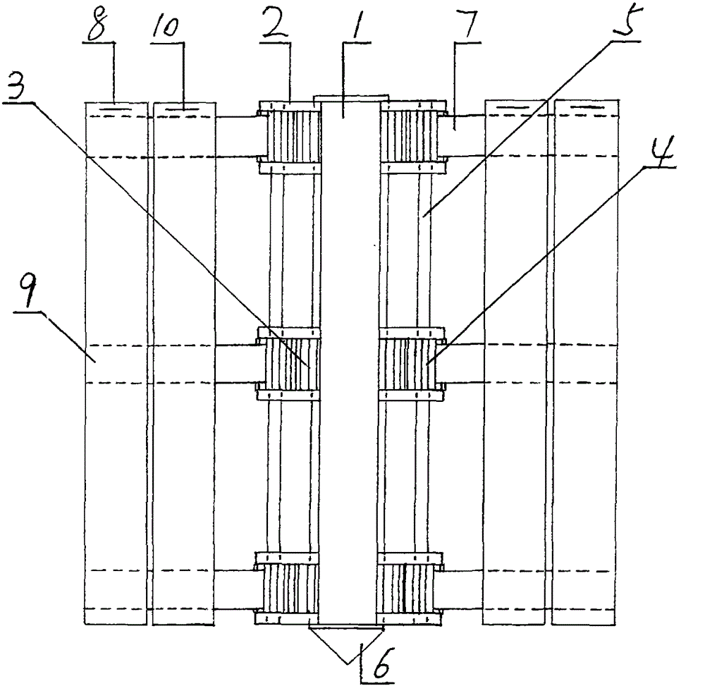
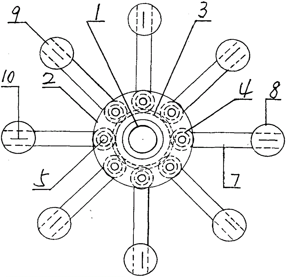
[0006] Such as figure 1 , 2 As shown, a rotary guide frame for the prefabrication of the shaft wall, this guide frame has the function of changing diameter, that is, it can be large or small, so as to achieve the general purpose. Its structure is made up of central column 1, circular ring 2, rotating disc 3, gear 4, gear shaft 5, guide arm 7 and vertical beam 8. The central column 1 is a section of hollow cylinder, and its bottom is a cone 6, which is beneficial to align and locate the center of the circle on the basis. There are several rings 2 on the central column 1, and the rings 2 are in groups of two, and a rotating disk 3 is arranged in the middle of each group of rings 2, and the rotating disk 3 and the rings 2 are set on the central column 1 together. Above, each group of circular rings 2 and the center column 1 are fixedly connected into one body, and the circular rings 2 play a role in positioning the rotating disk 3 . The rotating disk 3 is located between the t...


PUM


Abstract

A rotary type guiding frame for prefabricating a well wall is structurally composed of a center column, rings, rotating discs, gears, gear shafts, guiding arms and vertical beams. The rings and the rotating discs are arranged on the center column, the gears are arranged between the rings and meshed with the rotating discs, the guiding arms are symmetrically arranged on the outer side of each gear, the outer end of each guiding arm is provided one vertical beam, and after assembly, the vertical beams, the guiding arms and the gear shafts form a cuboid frame. When any one vertical beam mounted on the center column is rotated, the other vertical beams can all synchronously rotate in the same direction under the driving of the gear shafts and the rotating discs, so that the diameter of the guiding frame is adjusted.

Description

technical field [0001] A rotary guide frame belongs to the field of mining equipment. Background technique [0002] In the construction of shaft wellbore, using large drilling rig to sink well is one of the most advanced mechanized well formation. Its well wall is a prefabricated part of reinforced concrete, and its diameter usually varies between 4-9 meters. In the prefabrication process, firstly, a guide frame should be set up on the foundation (platform) of the prefabricated well wall as a support for fixing the inner and outer formwork and the reinforcement cage. Due to the change of the well, this has just caused a guide frame to be redone every time a wellhead is excavated, causing a lot of waste. Contents of the invention [0003] The purpose of this application is to provide a rotary guide frame for shaft wall prefabrication. This guide frame has the function of changing the diameter, that is, it can be large or small, so as to achieve the general purpose. Its s...

Claims


Application Information

Patent Timeline
Patent Type & Authority Patents(China)
IPC IPC(8): E21D7/00
Inventor 冯莉莉
Owner 南通宾尼织造有限公司
Why Eureka
Try Eureka