
Rotatable machine gripper

A gripper and machine technology, applied in the field of rotatable robot grippers, can solve the problems of difficult grasping, positioning, and 360-degree rotation of grasped objects, so as to achieve flexible control of rotation and opening and closing, and grasp workpieces Convenience and wide range of expansion and contraction

Inactive Publication Date: 2013-08-07
ANHUI UNIVERSITY
View PDF9 Cites 16 Cited by
  • Summary
  • Abstract
  • Description
  • Claims
  • Application Information

AI Technical Summary

Problems solved by technology

[0002] The robot gripper is a robot part that can realize the function similar to the human hand. The robot gripper is a part used to hold the workpiece or tool. It is one of the important actuators. According to the shape of the workpiece held by the robot, the gripper can be divided into Various types: mechanical grippers, magnetic chucks, welding guns and general-purpose grippers. The rotation angle of the grippers in the prior art is not enough, the opening and closing degree of the grippers is too small, it is not flexible to use, and it is easy to grasp loosely. When used at night , it is not easy to locate, and it cannot be rotated 360 degrees, and the grabbing object in a special position is not easy to grab

Method used


Image

  • Rotatable machine gripper
  • Rotatable machine gripper
  • Rotatable machine gripper

Examples


Embodiment Construction

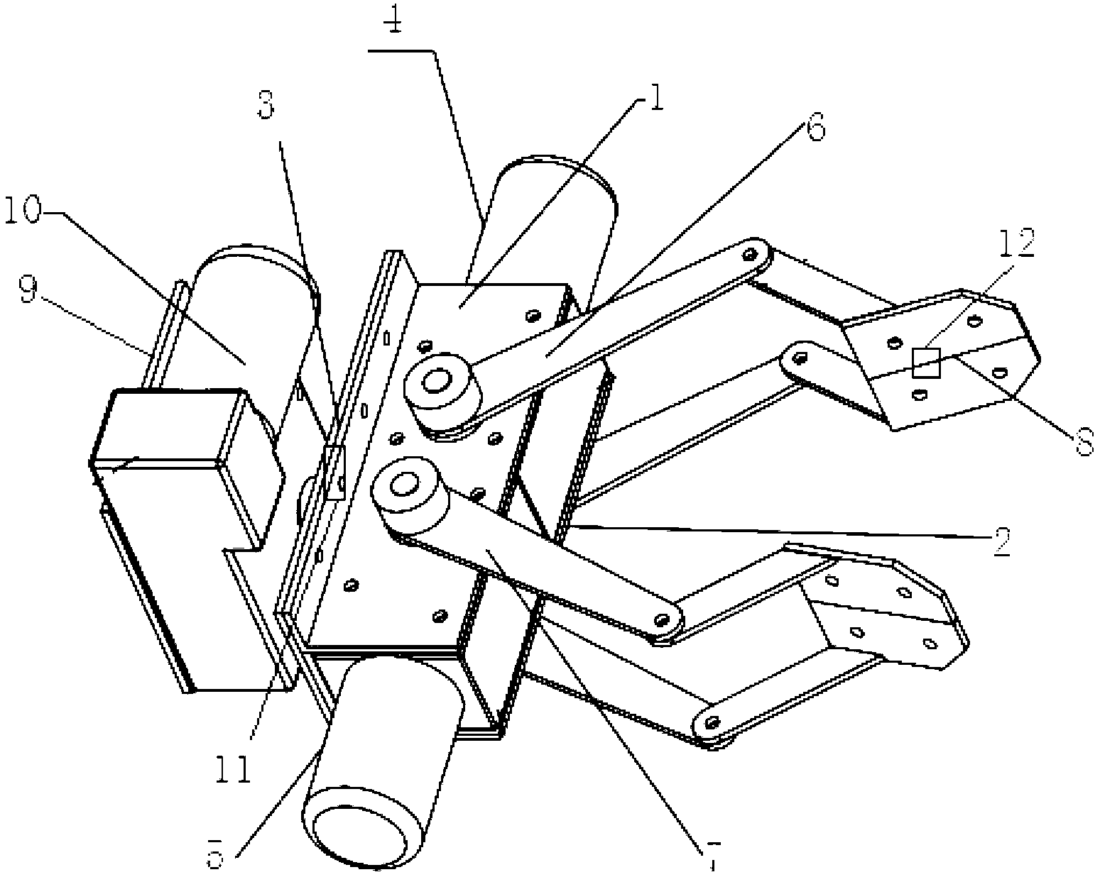
[0013] Such as figure 1 As shown, a rotatable robot gripper includes a rotating part, a positioning part and a finger part, and the positioning part includes an upper base plate 1, a lower base plate 2 and a back plate 3, and the upper base plate 1 and The side of the lower base plate 2 is fixed on the front of the back plate 3, and the front and rear sides between the upper and lower base plates 1 and 2 are respectively fixedly installed with a worm gear reducer motor 1 and a worm gear reducer motor 2 5; the finger part includes The left finger 6 and the right finger 7, the left and right fingers 6, 7 are composed of two rotatable L-shaped push rods placed in parallel, and polygonal iron sheets are fixedly installed on one end of the two L-shaped push rods 8. The two L-shaped push rods of the left finger 6 are connected to the worm gear motor-4 respectively, and the two L-shaped push rods of the right finger 7 are respectively connected to the worm gear motor two 5 connectio...


PUM


Abstract

The invention discloses a rotatable machine gripper. A first worm gear motor and a second worm gear motor are fixedly arranged on the front side and the rear side between an upper base plate and a lower base plate respectively; a finger portion comprises a left finger and a right finger which are respectively formed by two parallelly arranged rotatable L-shaped pushing rods; a polygonal iron piece is fixedly arranged at one end of every L-shaped pushing rod; a rotation portion comprises a second back plate; and a third worm gear motor which is fixedly arranged on the second back plate is connected with the back of a first back plate. The rotatable machine gripper has the advantages of achieving 360 degree rotation of the machine gripper and being convenient to grab workpieces due to the worm gear motors and enabling rotation and opening and closing control of the machine gripper to be flexible and an extensible range to be large due to the facts that an opening and closing angle of the machine gripper is 160 degrees and the opening and closing degree is large.

Description

technical field [0001] The invention relates to the technical field of robot grippers, in particular to a rotatable robot gripper. Background technique [0002] The robot gripper is a robot part that can realize the function similar to the human hand. The robot gripper is a part used to hold the workpiece or tool. It is one of the important actuators. According to the shape of the workpiece held by the robot, the gripper can be divided into Various types: mechanical grippers, magnetic chucks, welding guns and general-purpose grippers. The rotation angle of the grippers in the prior art is not enough, the opening and closing degree of the grippers is too small, it is not flexible to use, and it is easy to grasp loosely. When used at night , It is not easy to locate, and it cannot be rotated 360 degrees. It is not easy to grab objects in special positions. Contents of the invention [0003] The object of the present invention is to provide a reliable rotatable robotic g...

Claims


Application Information

Patent Timeline
Patent Type & Authority Applications(China)
IPC IPC(8): B25J15/08B25J9/12B25J19/04B25J9/18
Inventor 李国丽王群京刘国华许家紫
Owner ANHUI UNIVERSITY
Learn More