Incremental electro-hydraulic digital flow control valve with double valve cores rotating oppositely

A digital flow, incremental technology, applied in valve details, multi-port valves, valve devices, etc., can solve problems such as incompatibility with the overall development of hydraulic technology, manufacturing and assembly wear errors, and reducing dynamic response speed. Output dead zone and inertial lag, radial hydraulic pressure balance, and the effect of increasing flow changes

Inactive Publication Date: 2013-12-11
HUAIHAI INST OF TECH
View PDF7 Cites 18 Cited by
  • Summary
  • Abstract
  • Description
  • Claims
  • Application Information

AI Technical Summary

Problems solved by technology

However, due to the manufacturing, assembly and wear errors of the ball screw or cam mechanism, a certain zero dead zone is caused and the dynamic response speed is reduced
In addition, the resolution of this valve is not high, which limits its application in high-precision electro-hydraulic control systems
Although incremental digital valves are technically more mature than fast-switching digital valves, overall, the development of electro-hydraulic digital valves is still slow, which is not compatible with the overall development of hydraulic technology, and new types of electro-hydraulic valves need to be developed and researched. Liquid digital valve

Method used


Image

  • Incremental electro-hydraulic digital flow control valve with double valve cores rotating oppositely
  • Incremental electro-hydraulic digital flow control valve with double valve cores rotating oppositely
  • Incremental electro-hydraulic digital flow control valve with double valve cores rotating oppositely

Examples


Embodiment Construction

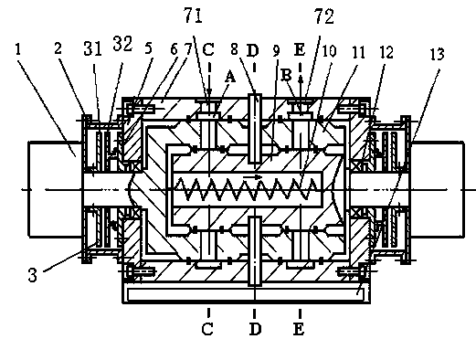
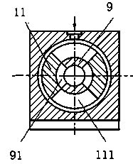
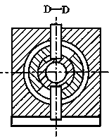
[0032] A double-spool counter-rotating incremental electro-hydraulic digital flow control valve, such as figure 1 shown. The control valve includes a valve body 7 , an outer spool 11 , an inner spool 9 , a stepper motor 1 , a stepper motor controller 13 , a spool angular displacement sensor 3 , a positioning pin 8 and a spool return spring 10 . Valve body 7 outer square inner circles are fixed with screws at the left and right end covers 5 . The outer surface of the valve body is square, and the outer surface of the valve body is provided with an oil inlet, an oil outlet and a stepping motor controller. The oil inlet annular groove A, and the oil outlet annular groove B communicated with the oil outlet. Both the outer spool and the inner spool are foot-cup-shaped, the large open end is a cylindrical sleeve, and the small closed end is a cylindrical shaft; the outer fan-shaped inlet corresponding to the oil inlet annular groove A is arranged on the surface of the outer spool ...


PUM


Abstract

The invention discloses an incremental electro-hydraulic digital flow control valve with double valve cores rotating oppositely. The control valve is characterized in that a valve body is square outside and circular inside, an oil inlet hole and an oil outlet hole are formed in the outer surface of the valve body and communicated with an annular oil inlet groove and an annular oil outlet groove in the circular-arc inner surface of the valve body respectively, an inner valve core and an outer valve core are both in a cylinder foot cup shape, the open end of the inner valve core is inserted in the open end of the outer valve core, the inner valve core and the outer valve core are installed inside the valve body together, and the inner valve core, the outer valve core and the valve body are kept coaxial; fan-shaped oil inlet holes and fan-shaped oil outlet holes are formed in the cylindrical surfaces of the inner valve core and the outer valve core, and respectively connected with the oil inlet hole and the oil outlet hole in the outer surface of the valve body through the annular oil inlet groove and the annular oil outlet groove in the inner surface of the valve body; the closed ends of the inner valve core and the outer valve core are provided with cylindrical shafts which penetrate through the left end cover and the right end cover of the valve body after passing through a bearing, and respectively connected with a stepping motor. Compared with an existing incremental sliding type digital flow valve, the digital valve disclosed by the invention has higher resolution ratio, dynamic response speed and flow control accuracy.

Description

technical field [0001] The invention relates to a hydraulic control element, in particular to a double-spool counter-rotating incremental electro-hydraulic digital flow control valve. Background technique [0002] Using computer to control the electro-hydraulic system is the trend of hydraulic technology development in the future. However, the electro-hydraulic proportional valves or servo valves widely used in electro-hydraulic systems can only be controlled by continuously changing voltage or current signals, while the instructions of the computer are pulse digital signals. Therefore, the control system must have a D / A (digital-to-analog) conversion device, resulting in a complex system, high cost, and reduced reliability. The emergence of digital valves has opened up a new way for the application of computers in the field of hydraulic pressure. The electro-hydraulic digital valve can be directly connected with the computer without D / A conversion. Compared with serv...

Claims


Application Information

Patent Timeline
Patent Type & Authority Applications(China)
IPC IPC(8): F16K11/06F16K31/04
Inventor 石延平刘成文侯金柱陈邵鹏
Owner HUAIHAI INST OF TECH
Why Eureka
Try Eureka