Electronic expansion valve

a technology of electric expansion valve and magnetic rotor, which is applied in the direction of valve operating means/releasing devices, mechanical equipment, fluid circulation arrangement, etc., can solve the problems of poor flexibility of magnetic rotor, easy drop of magnetic powder on magnetic rotor, bulky electronic expansion valve, etc., and achieves the effect of rotating more flexibly

Active Publication Date: 2013-10-15
ZHEJIANG SANHUA INTELLIGENT CONTROLS CO LTD
View PDF22 Cites 17 Cited by
  • Summary
  • Abstract
  • Description
  • Claims
  • Application Information

AI Technical Summary

Benefits of technology

[0008]It can be known from the above technical solution that, the electronic expansion valve according to the embodiments of the invention enables the magnetic rotor not subject to an axial force transmitted by the screw rod and rotate flexibly due to the fact that the output shaft is slidably connected to the screw rod in the axial direction and drivably connected to the screw rod in the circumferential direction.

Problems solved by technology

In the prior art, a stop rod, a slip ring and a spring rail are all arranged outside the magnetic rotor and thus the electronic expansion valve is bulky.
Since the magnetic rotor and the screw rod are fixedly connected in an axial direction so that the magnetic rotor still subjects to a downward axial force transmitted from the valve needle by the screw rod, the magnetic rotor is poor in flexibility.
Furthermore, since the stop rod is integrally formed with the magnetic rotor by injection molding, magnetic powder on the magnetic rotor will easily drop off during the course of stopping moving, and the matching margin between the stop rod and the slip ring is small.
In addition, since the slip ring and the spring rail are mounted at the cylindrical portion protruding from a valve seat which is formed by stretching process, it is very difficult to guarantee the coaxiality of the cylindrical portion protruding from the valve seat.
Besides, the core of valve seat consumes too much material and tends to make noise.

Method used


Image

  • Electronic expansion valve
  • Electronic expansion valve
  • Electronic expansion valve

Examples


first embodiment

[0013]The embodiment of the invention provides an electronic expansion valve including a magnetic rotor and a screw rod. The electronic expansion valve further includes an output shaft on which the magnetic rotor is surroundingly provided. The output shaft is slidably connected to the screw rod in an axial direction and drivably connected to the screw rod in the circumferential direction.

[0014]There are several connecting manners between the output shaft and the screw rod. In the first manner, a non-circular hole is provided at the lower end of the output shaft or at the upper end of the screw rod, and a post corresponding to the hole is provided at the upper end of the screw rod or at the lower end of the output shaft, the post being inserted into the hole. In the first manner, if the diameter of the lower end of the output shaft is larger than that of the upper end of the screw rod, the non-circular hole is provided at the lower end of the output shaft and the post corresponding t...

second embodiment

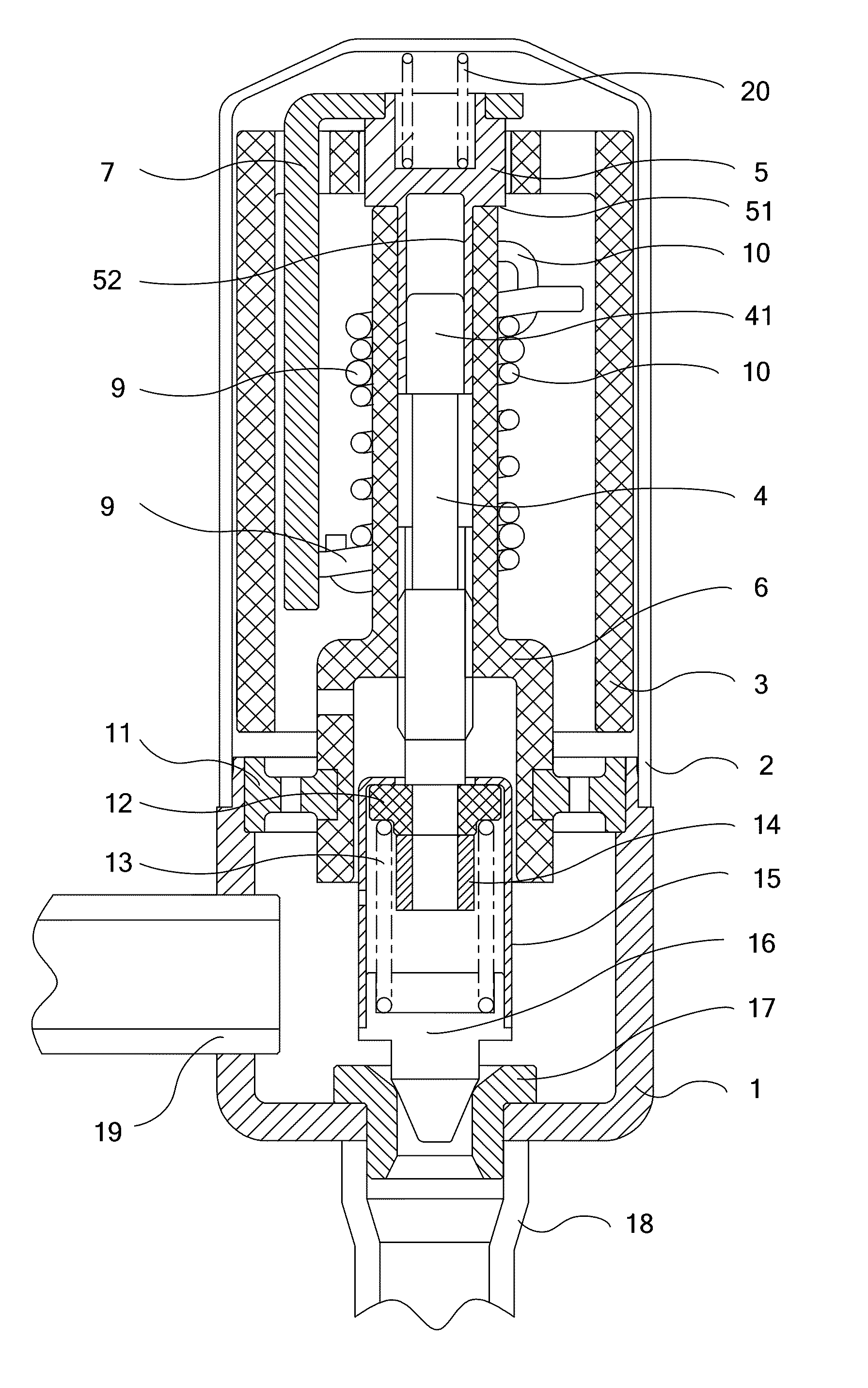
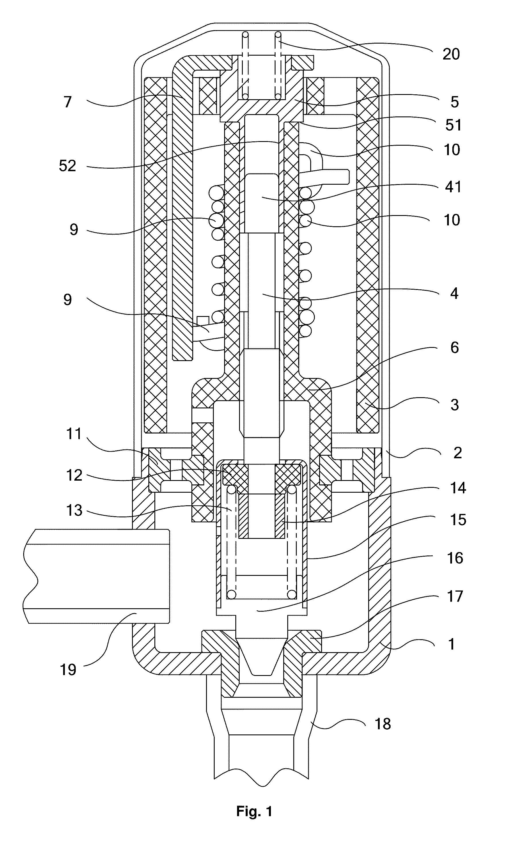
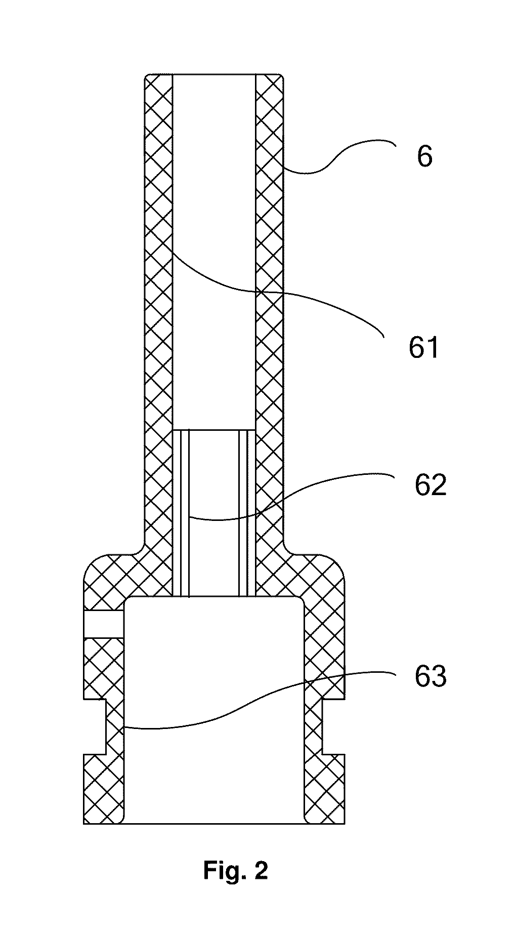
[0020]FIG. 1 is a schematic structural view of the electronic expansion valve according to a second embodiment of the invention, and FIG. 2 is a schematic structural view of the nut in the electronic expansion valve according to the second embodiment of the invention. As shown in FIGS. 1 and 2, the second embodiment of the invention is based on the first embodiment described above. The difference between the two embodiments lies in that, the electronic expansion valve according to the second embodiment can further include a nut positioning seat 11 fixedly provided on a valve seat 1 of the electronic expansion valve. The nut 6 is of a cylindrical shape, the lower portion of the nut 6 is fixedly provided on the nut positioning seat 11. The spring rail 10, on which the slip ring 9 is slidably provided, is surroundingly provided on the cylindrical surface of the upper portion of the nut 6. A first guiding section 61 and an internal thread section 62 are arranged inside the nut 6 in sequ...

third embodiment

[0028]FIG. 3 is a schematic structural view of the electronic expansion valve according to a third embodiment of the invention. As shown in FIG. 3, the third embodiment of the invention is based on the first embodiment described above. The difference between the first and third embodiments lies in that the electronic expansion valve according to the third embodiment further includes: a support seat 21 fixedly provided on the valve seat 1 of the electronic expansion valve and a support sleeve 22 arranged between the nut 6 and the spring rail 10. The lower portion of the support sleeve 22 is fixedly provided on the support seat 21. The nut 6 is fixedly provided inside the support sleeve 22. The spring rail 10 on which a slip ring 9 is slidably provided is surroundingly provided on the outer surface of the support sleeve 22. The lower end of the output shaft 5 is inserted in the upper portion of the support sleeve 22. The top end of the support sleeve 22 abuts against the support surfa...


PUM


Abstract

Embodiments of the invention provide an electronic expansion valve, including a magnetic rotor and a screw rod, and further including an output shaft. The magnetic rotor is surroundingly provided on the output shaft, and the output shaft is slidably connected to the screw rod in an axial direction and drivably connected to the screw rod in a circumferential direction. Since the output shaft is slidably connected to the screw rod in an axial direction and drivably connected to the screw rod in a circumferential direction, the magnetic rotor does not subject to an axial force transmitted by the screw rod and rotates flexibly.

Description

CROSS-REFERENCES TO RELATED APPLICATIONS[0001]This application claims the benefit of priority to Chinese Application No. 200910089403.7 filed on Jul. 17, 2009.FIELD OF THE INVENTION[0002]Embodiments of the present invention relate to a valve, in particular to an electronic expansion valve.BACKGROUND OF THE INVENTION[0003]Conventional electronic expansion valve makes use of the principle of a step-motor, in which a magnetic rotor member is driven by a coil to rotate in a forward direction and a reversed direction and a rotation movement of the magnetic rotor member is transformed into an up-and-down movement of a screw rod. A valve needle which is connected to and driven by the screw rod moves up and down to control the amount of flow of the electronic expansion valve.[0004]In the prior art, a stop rod, a slip ring and a spring rail are all arranged outside the magnetic rotor and thus the electronic expansion valve is bulky. Besides, the magnetic rotor and the screw rod are fixedly c...

Claims


Application Information

Patent Timeline
Patent Type & Authority Patents(United States)
IPC IPC(8): F16K31/02
CPCF16K31/047F25B41/062F25B2341/065Y02B30/72Y02B30/70F25B41/34F25B41/35
Inventor LV, MINGZHAN, CAIYI
Owner ZHEJIANG SANHUA INTELLIGENT CONTROLS CO LTD
Why Eureka
Try Eureka