Cage type multi-shaft optical system mounting rack

A technology of optical system and mounting frame, which is applied in the field of optical system installation and adjustment mechanism, and can solve problems such as difficulty in changing relative distance, time-consuming and labor-intensive precision, and large operating platform area

Active Publication Date: 2014-05-28
锐光凯奇(镇江)光电科技有限公司
View PDF8 Cites 10 Cited by
  • Summary
  • Abstract
  • Description
  • Claims
  • Application Information

AI Technical Summary

Problems solved by technology

[0002] The existing optical element mounting bracket has a complex structure, occupies a large area of ​​the operating platform, and the installation position of the optical element is limited
For parallel optical paths, each optical element needs to be adjusted individually, which is time-consuming and laborious, and the accuracy is difficult to guarantee. Once the relative distance between the two optical elements is fixed, it is also difficult to change.
In order to solve the above problems, some cage-type single-axis optical component mounting brackets have appeared on the market, but for an optical system with only one central axis, it is not easy to cooperate with other devices or systems with different heights after the optical path is fixed.

Method used


Image

  • Cage type multi-shaft optical system mounting rack
  • Cage type multi-shaft optical system mounting rack
  • Cage type multi-shaft optical system mounting rack

Examples


specific Embodiment approach 1

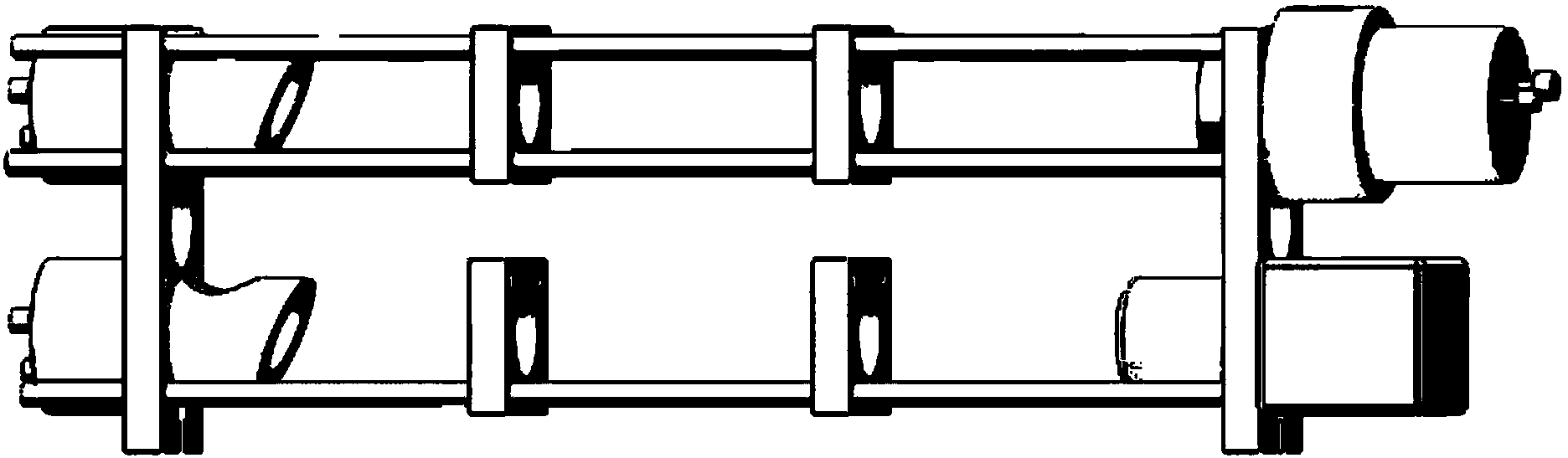
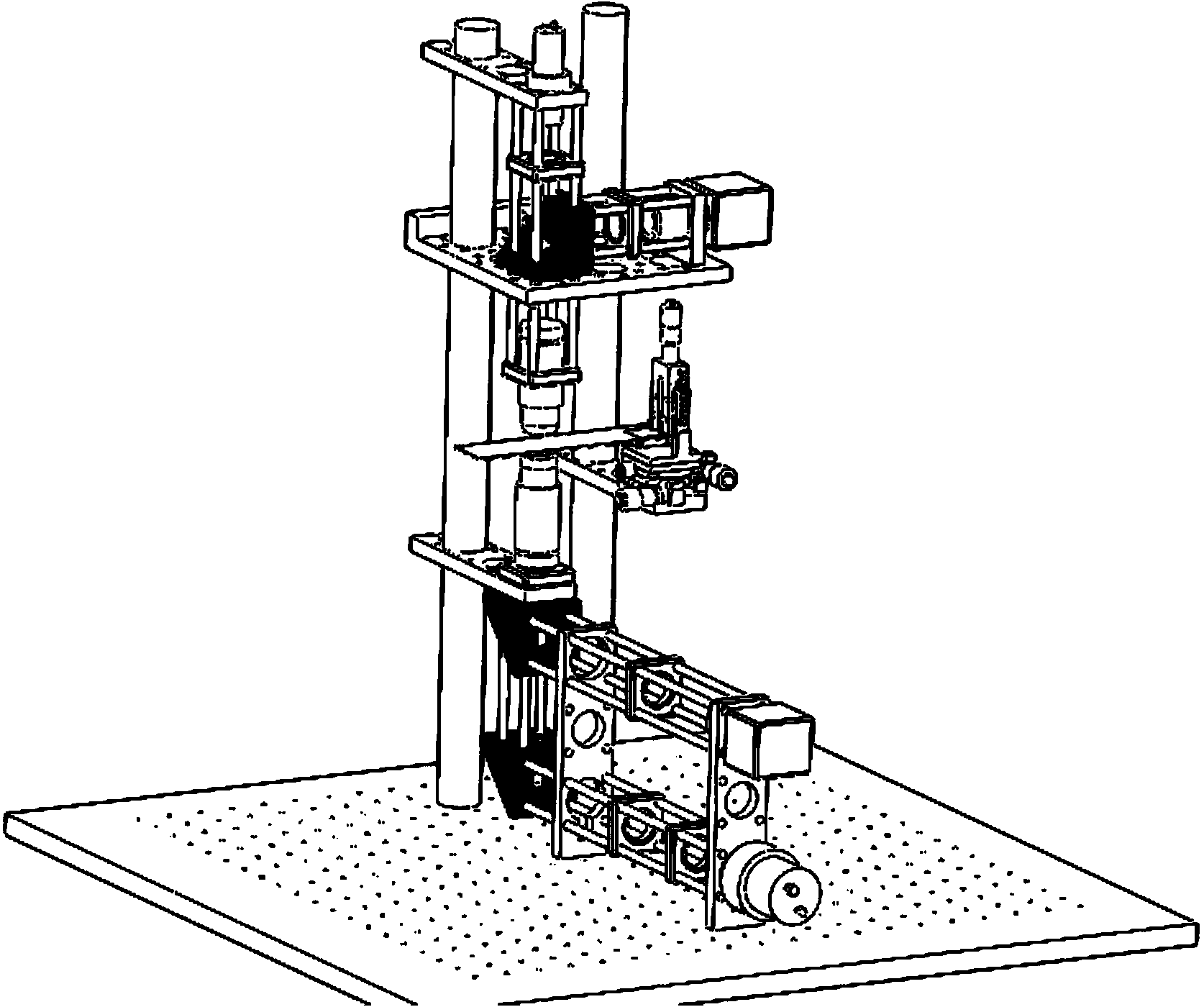
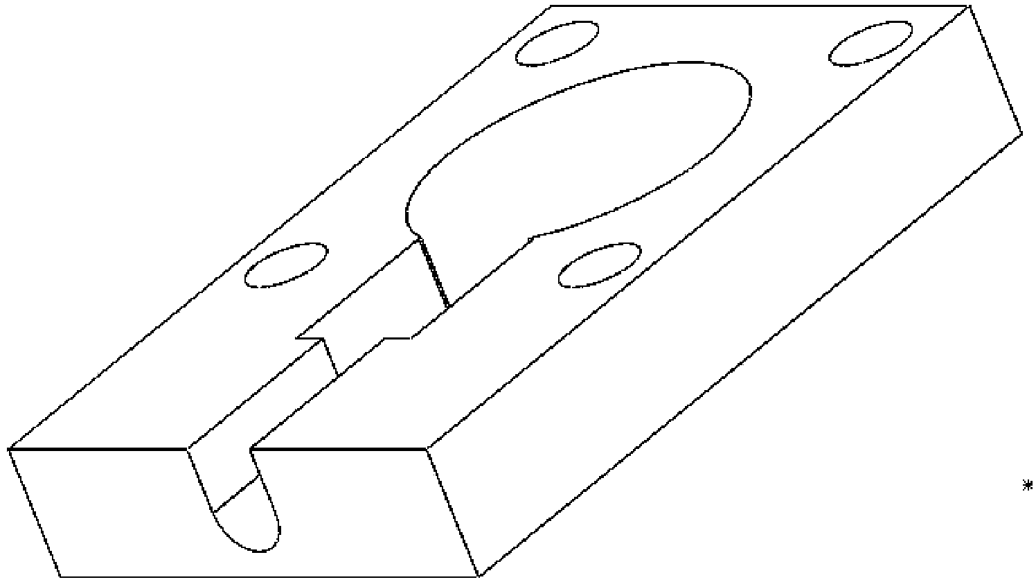
[0018] Specific implementation mode one: combine figure 1 and figure 2 To illustrate this embodiment, the cage-type multi-axis optical system mounting frame described in this embodiment includes at least two optical element mounting frames and at least two guide rods, and at least one optical element mounting hole is provided on the optical element mounting frame, Four guide rod mounting holes are evenly distributed on the outside of each optical component mounting hole, and the guide rods pass through the guide rod mounting holes of multiple optical component mounting frames in turn, and the bottoms of at least two optical component mounting frames are provided with mounting frame fixing holes , the mounting frame fixing hole is used to fix the cage multi-axis optical system mounting frame on the optical table.

[0019] The cage-type multi-axis optical system mounting frame described in this embodiment includes multiple optical element mounting frames and multiple guide rod...

specific Embodiment approach 2

[0020] Specific implementation mode two: combination figure 2 Describe this embodiment. This embodiment is a further limitation of the cage-type multi-axis optical system mount described in Embodiment 1. In this embodiment, the cage-type multi-axis optical system mount further includes N pillars, and N is a positive integer, the pillars are cylindrical, and each pillar fixes at least one optical element mounting frame, and the optical element mounting frame is fixed on the pillar through any optical element mounting hole thereon.

[0021] In practical applications, the optical element mounting frame is fixedly connected to the pillar through a jacking screw. When there is 45-degree reflection in the optical path, the pillar can be fixed vertically on the optical platform, and the pillar can be inserted through the optical element mounting holes on one or more optical element mounting frames according to actual needs, and other optical element mounting frames can be fixed on t...

specific Embodiment approach 3

[0022] Specific Embodiment Three: This embodiment is a further limitation of the cage-type multi-axis optical system mounting frame described in Embodiment 2. In this embodiment, the optical element mounting frame is also provided with threaded holes, and the threaded The holes are used to fix the optical adjustment mount.

[0023] In this embodiment, the optical adjustment frame is installed on the optical element mounting frame, and other optical elements are added to the optical adjustment frame to meet the needs of different optical systems, and the propagation of light in space can be realized.


PUM


Abstract

The invention discloses a cage type multi-shaft optical system mounting rack and relates to an optical system mounting and adjusting mechanism, for solving the problem that the conventional optical element mounting rack is not applicable to multi-optical axis systems. When the mounting rack is used, guide rods, optical element mounting racks and support columns are assembled together as required; the guide rods sequentially pass through guide rod mounting holes of a plurality of optical element mounting racks, so as to achieve the multi-shaft optical system structure; when 45 degrees reflection is formed in a light path, the support columns can be fixed on one optical platform and penetrate through optical element mounting holes of one or more optical element mounting racks, and spreading of the light along the direction perpendicular to the optical platform is realized. As the heights and the direction of all the shafts of the mounting rack can be flexibly adjusted, the mounting rack can be easily used together with other devices or systems of different heights, the optical system is compact in structure; establishment of the multi-shaft optical system in a plane and the establishment of the multi-shaft optical system in a space are achieved. The mounting rack is applicable to establishment of multi-shaft optical systems.

Description

technical field [0001] The invention relates to an optical system installation adjustment mechanism. Background technique [0002] The existing optical element mounting bracket has a complex structure, occupies a large area of ​​the operation platform, and the installation position of the optical element is limited. For parallel optical paths, the angle of each optical element needs to be adjusted independently, which is time-consuming and laborious, and the accuracy is difficult to guarantee. Once the relative distance between two optical elements is fixed, it is also difficult to change. In order to solve the above problems, some cage-type single-axis optical component mounting brackets have appeared on the market, but for optical systems with only one central axis, it is not easy to cooperate with other devices or systems with different heights after the optical path is fixed. Contents of the invention [0003] The object of the present invention is to provide a cage-t...

Claims


Application Information

Patent Timeline
Patent Type & Authority Applications(China)
IPC IPC(8): G02B7/00
CPCG02B7/02
Inventor 刘书钢熊望娥
Owner 锐光凯奇(镇江)光电科技有限公司
Why Eureka
Try Eureka