Fuel tank cap lock with a reduced number of components

A storage tank cover and equipment technology, applied in the direction of connecting components, mechanical equipment, building locks, etc., can solve the problems of high assembly cost, susceptibility to interference, complex structure, etc.

Active Publication Date: 2014-05-28
KIEKERT AG
View PDF8 Cites 14 Cited by
  • Summary
  • Abstract
  • Description
  • Claims
  • Application Information

AI Technical Summary

Problems solved by technology

In this case, the previously used mechanisms are structurally very complex and have multiple components
As a result, a stronger drive is required for the closing process, which is usually controlled by a central locking device
Multiple structurally complex parts also lead to high assembly costs and susceptibility to interference

Method used


Image

  • Fuel tank cap lock with a reduced number of components
  • Fuel tank cap lock with a reduced number of components
  • Fuel tank cap lock with a reduced number of components

Examples


Embodiment Construction

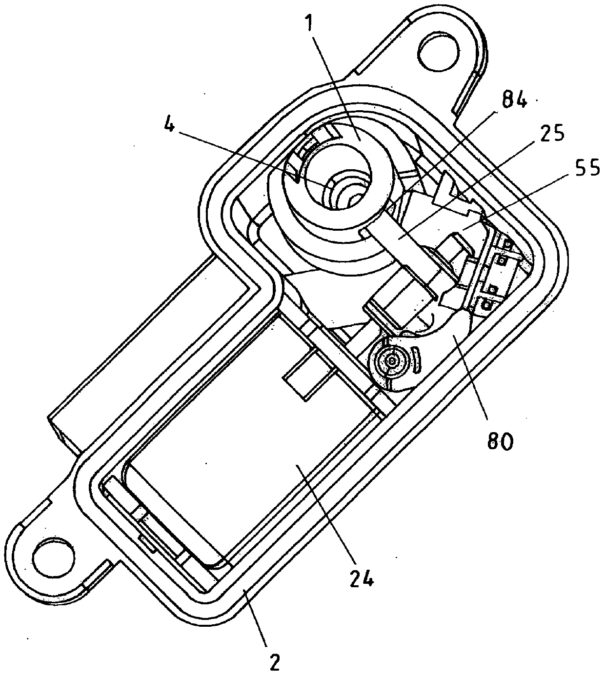
[0045] figure 1 A view of the interior of the lock device is shown with the locking pin 1 in the open position. In order to make the illustration more intuitive, only a part of the housing 2 is shown which is marked with the corresponding reference number. On its peripheral surface 7 the locking pin 1 has a sliding guide 5 which, in cooperation with the pin 18 , serves as a positive guide 8 between the locking pin 1 and the housing 2 . The reference number 24 designates a drive in the form of a motor for the locking pawl 25 by means of which the locking pin 1 is fixed in the locked position so that it cannot be actuated further.

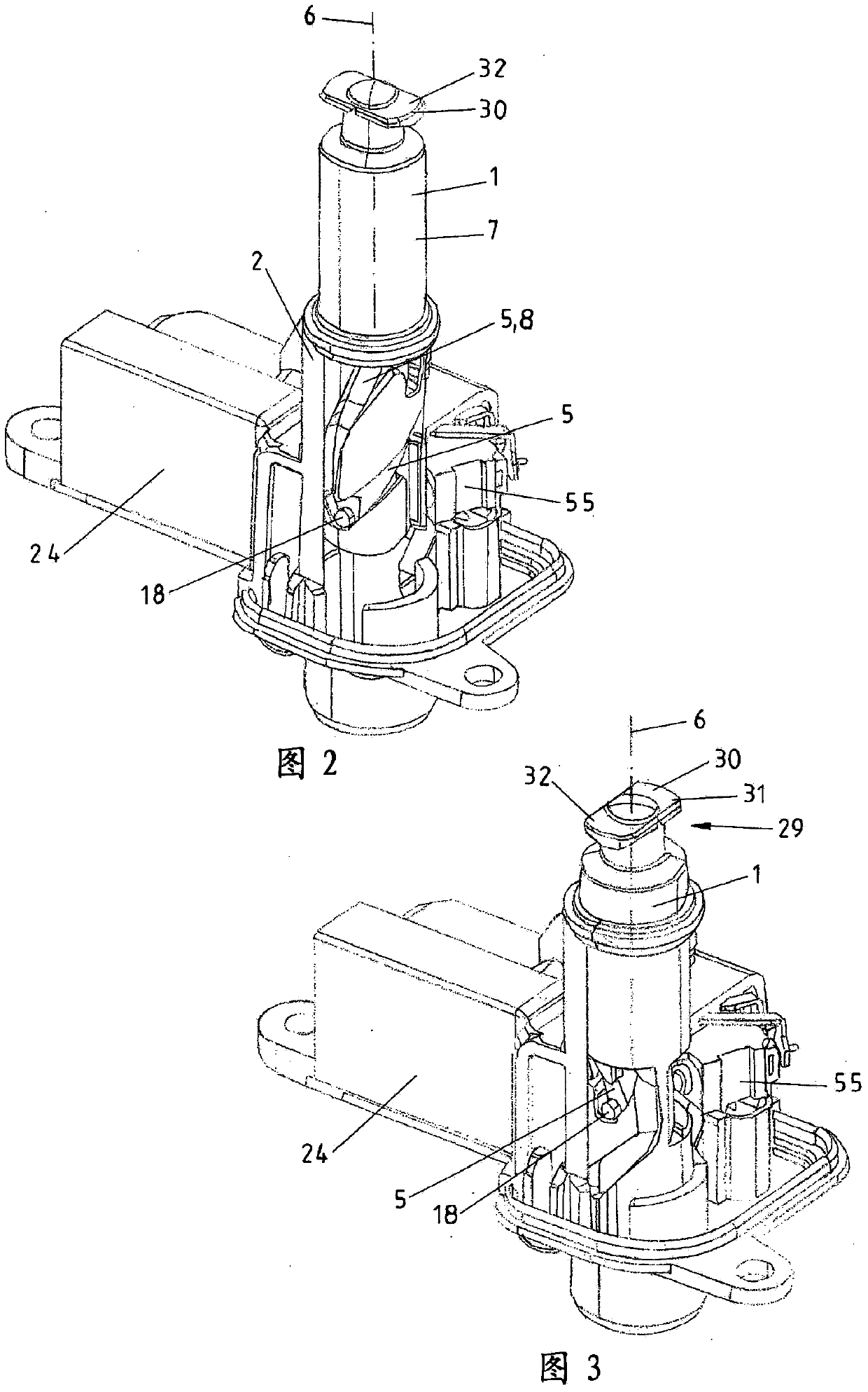
[0046] in accordance with figure 2 In the schematic diagram of , the locking pin 1 is placed in its closed position, that is to say pressed down along its longitudinal axis 6 . This is achieved by a tank cover or charging cover, not visible here, with which the locking pin 1 is in contact at its upper end 19 . Effective for this is a mechanism 3...


PUM


Abstract

The invention relates to a lock for a fuel tank cap or tailboard in a vehicle, comprising a locking bolt (1) which can be adjusted between an open and a closed position by opening and closing the cap or tailboard. Said fuel tank cap lock, in the housing (2) of the lock, is positively driven counter to the force of a compression spring (4) in the direction of its longitudinal axis (6) and about its longitudinal axis (6).

Description

technical field [0001] The invention relates to a lock device for a tank lid / fuel tank lid or charging lid in a vehicle, having a locking pin movable between an open position and a closed position by opening and closing the tank lid or charging lid . Background technique [0002] For example DE 10 2011 076 810 discloses a locking device for a tank lid. The tank lid is closed manually at the end of the tank operating process, wherein force is applied to the latch to move the latch from its out-of-out open position to its in-in closed position. When the tank cover is actuated, the (lock) pin is simultaneously rotated about its longitudinal axis and is thus fixed in the tank cover at its end facing the tank cover, so that a latch is produced. In this case, the previously used mechanisms are structurally very complex and have multiple components. As a result, a stronger drive is also required for the closing process, which is normally controlled by a central locking device. ...

Claims


Application Information

Patent Timeline
Patent Type & Authority Applications(China)
IPC IPC(8): E05B83/00E05C19/02B60K15/05
CPCB60K2015/053E05C19/022B60K15/05E05B83/34B60K2015/0546B60K2015/0576B60K2015/0584B60Y2400/90Y10T292/0834Y10T292/0837Y10T292/084Y10T292/0864Y10T292/0868Y10T292/096Y10T292/1005Y10T292/101Y10T292/1013Y10T292/1014Y10T292/1016Y10T292/54B60K2015/0515B60K2015/0561E05C19/02E05C19/028E05C19/06E05C19/16E05C19/165
Inventor M·S·巴萨瓦拉加帕H·瓦曼
Owner KIEKERT AG
Why Eureka
Try Eureka