

Labyrinth seal
A labyrinth sealing and sealing element technology, applied in the direction of engine sealing, engine components, machines/engines, etc., can solve problems such as large leakage loss
- Summary
- Abstract
- Description
- Claims
- Application Information
AI Technical Summary
Problems solved by technology
Method used
Image

Examples
Embodiment Construction
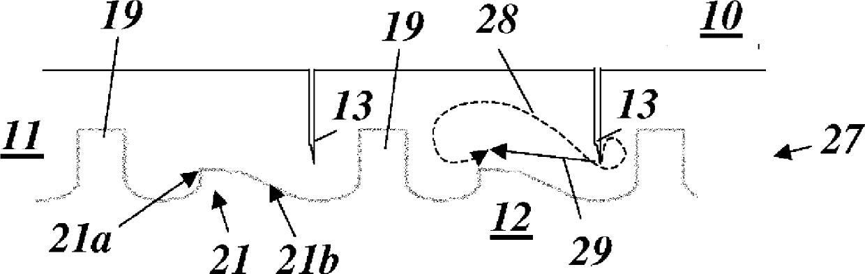
[0038] figure 2 with figure 1 A similar view shows a first exemplary embodiment of a labyrinth seal according to the invention. with according to figure 1 Different from the seals, the sealing strip 13 on the stator side is arranged asymmetrically in each case, at figure 1 In each case, the stator-side sealing strip 13 is arranged symmetrically centrally between the two rotor-side sealing strips. The distance b from the sealing strip 13' on the stator side to the next adjacent sealing strip 14b on the right rotor side is the distance from the sealing strip 13' on the stator side to the next adjacent sealing strip 14a on the left rotor side Part of a (the ratio of b to a is less than 1). figure 2 The cold-installed state of the labyrinth seal 25 is shown. Also shown is the transient movement 28 of the sealing tip of the stator-side sealing strip 13 relative to the rotating part 12 . The overall motion from the cold state to the steady state is shown. The resulting tran...
PUM
 Abstract
Description
Claims
Application Information