
Locking structure used for sleeving inner pipe with outer pipe

A technology of locking structure and outer tube sleeve, applied in the direction of connecting member, rod connection, motor vehicle, etc., can solve the problems of tube deformation, locking too tight or loose, easy to cause danger, etc., and achieve consistent locking force. , Safe and reliable locking, firm socket effect

Inactive Publication Date: 2014-06-04
陈开明
View PDF0 Cites 0 Cited by
  • Summary
  • Abstract
  • Description
  • Claims
  • Application Information

AI Technical Summary

Problems solved by technology

This kind of bolt and nut locking method is easy to be locked too tight or too loose. When the lock is too tight, it is easy to deform the pipe; when the lock is too loose, it is easy to cause danger because the lock is not tight. Therefore, the current method of locking the inner and outer tubes with bolts and nuts needs to be improved in structure

Method used


Image

  • Locking structure used for sleeving inner pipe with outer pipe
  • Locking structure used for sleeving inner pipe with outer pipe
  • Locking structure used for sleeving inner pipe with outer pipe

Examples


Embodiment Construction

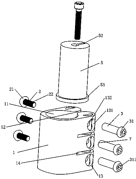
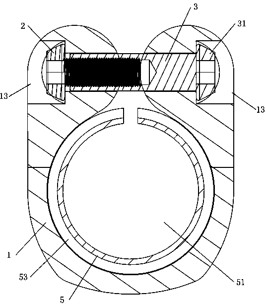
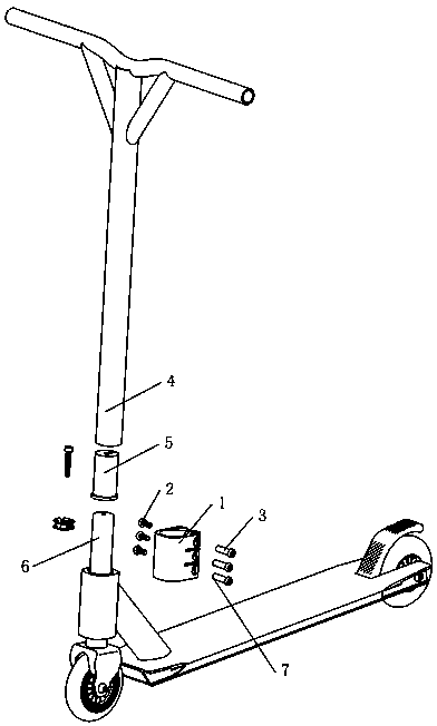
[0021] The present invention is a locking structure for inner and outer pipe sockets, such as figure 1 , 2 , 4, and 5, it includes an outer ring 1 with a hollow through hole 11, a locking bolt 2 and a nut 3, and a gap 12 communicating with the through hole 11 is opened on the outer ring 1, and in the gap 12 The two sides are respectively provided with transverse holes 13 for threaded connection of the locking bolt 2 to the nut 3, and the outer ring 1 is sleeved on the outer wall of the outer tube 4 through the through hole 11. Here, an inner sleeve 5 is also included, A sleeve hole 51 that can be sleeved on the outer wall of the end of the inner tube 6 is opened in the inner sleeve 5, and the vertical direction that communicates with the sleeve hole 51 and the horizontal direction that communicates with the upper end of the sleeve hole 51 are opened on the inner sleeve 5. The right-angled notch 52 in the middle of the direction; the outer tube 4 is inserted into the space bet...


PUM


Abstract

A locking structure used for sleeving an inner pipe with an outer pipe comprises an outer ring, locking bolts and nuts, wherein the outer ring is provided with a hollow through hole. The outer ring is provided with a notch communicated with the through hole. The two sides of the notch are respectively provided with a transverse hole, wherein the locking bolts penetrate through the transverse holes to be in threaded connection with the nuts. The outer wall of the outer pipe is sleeved with the outer ring through the through hole in the outer ring. The locking structure further comprises an inner sleeve. A sleeve hole is formed in the inner sleeve, wherein the outer wall of one end of the inner pipe can be sleeved with the sleeve hole. The inner sleeve is provided with a notch, wherein the notch is communicated with the sleeve hole in the vertical direction and communicated with the middle of the upper end of the sleeve hole in the horizontal direction. The outer pipe is inserted into the space between the outer wall of the inner sleeve and the inner wall of the outer ring. The locking bolts or the nuts are provided with partition parts used for controlling locking force. The locking structure is reasonable, the locking force is consistent, and locking is safer and more reliable.

Description

【Technical field】 [0001] The invention relates to a locking structure when a larger outer tube is sheathed on the end of a smaller inner tube. 【Background technique】 [0002] At this stage, in many products or tools, such as scooters, etc., it is often used to connect the inner and outer tubes together. At this time, a locking structure is needed. The current locking structures are basically The bolt and nut method is used, and the bolt is crossed through the locking ring and then the nut is screwed on to lock the ends of the inner and outer pipes. This kind of bolt and nut locking method is easy to be locked too tight or too loose. When the lock is too tight, it is easy to deform the pipe; when the lock is too loose, it is easy to cause danger because the lock is not tight. Therefore, the current method of locking the inner and outer pipes with bolts and nuts needs to be improved in structure. 【Content of invention】 [0003] The purpose of the present invention is to ov...

Claims


Application Information

Patent Timeline
Patent Type & Authority Applications(China)
IPC IPC(8): F16B7/04B62K17/00
Inventor 陈开明
Owner 陈开明
Learn More