Cup feeding mechanism of cup printing machine

A cup printing machine and cup feeding technology, which is applied to printing machines, rotary printing machines, printing, etc., can solve the problems of inaccurate printing alignment, lower printing quality, and complicated cup mold structure, so as to achieve stable conveying process and improve printing quality. quality, avoiding off-axis effects

Active Publication Date: 2018-12-11
广东金兴机械股份有限公司
View PDF7 Cites 0 Cited by
  • Summary
  • Abstract
  • Description
  • Claims
  • Application Information

AI Technical Summary

Problems solved by technology

This method often sucks two or three cups that are close together at one time, but only the outermost cup can be printed during printing, resulting in inaccurate printing alignment; in addition, it is necessary to set the suction head in the cup mold The driving and guiding structure of the suction head and the suction channel of the suction head must be set, which leads to a complicated structure of the cup mold, and the cup mold often has high precision to ensure the accuracy of printing, but the complicated structure of the cup mold often leads to the Accuracy is reduced, thereby reducing the quality of printing

Method used


Image

  • Cup feeding mechanism of cup printing machine
  • Cup feeding mechanism of cup printing machine
  • Cup feeding mechanism of cup printing machine

Examples


Embodiment Construction

[0020] Further description will be made below in conjunction with the accompanying drawings and preferred embodiments of the present invention.

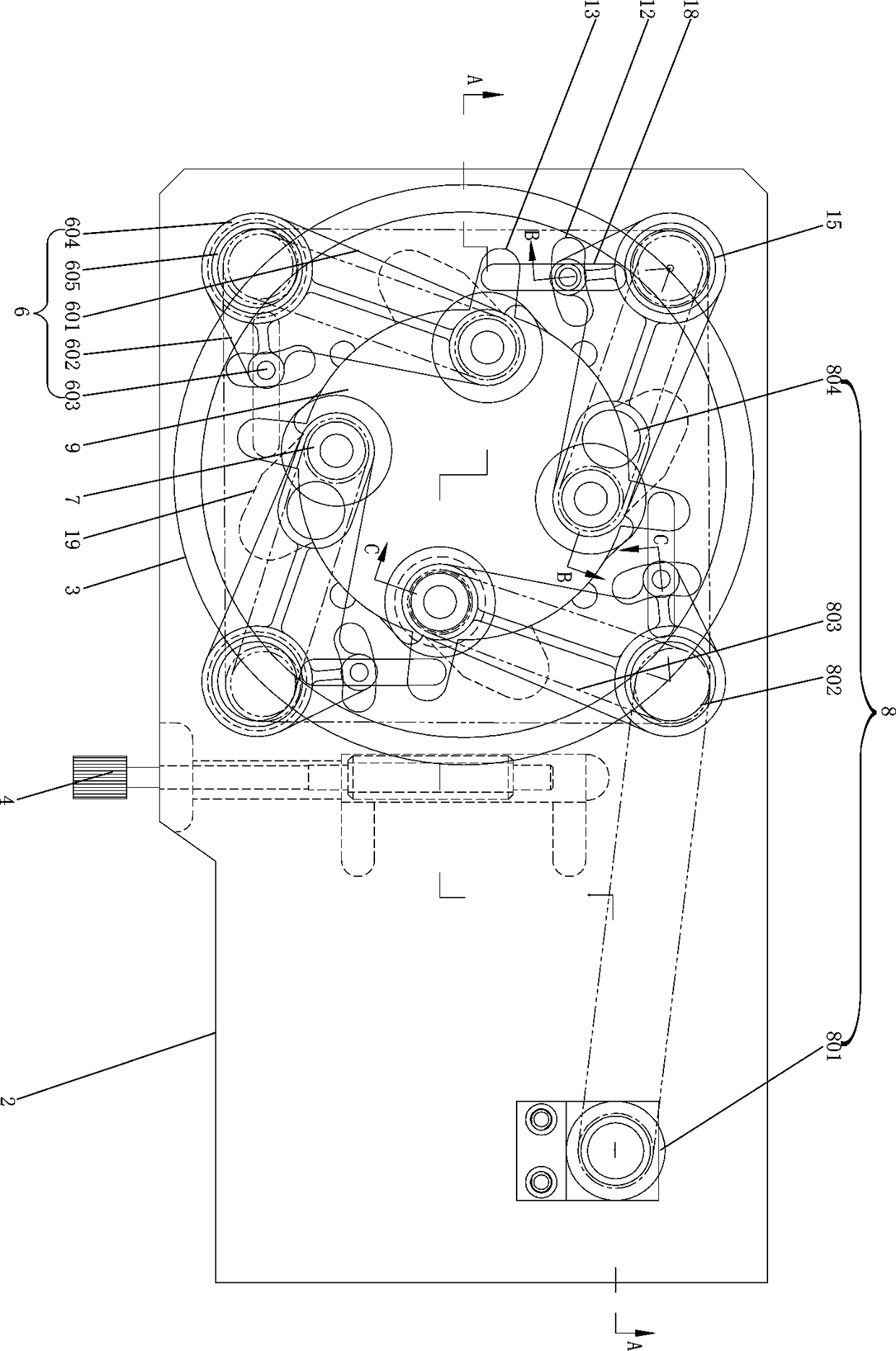
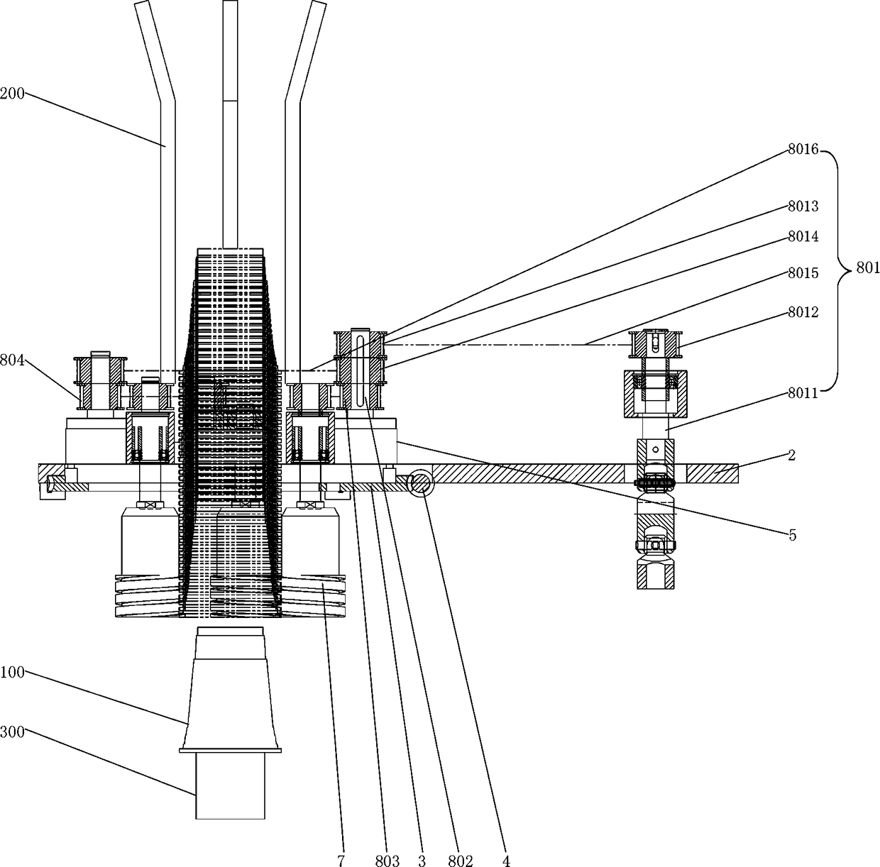
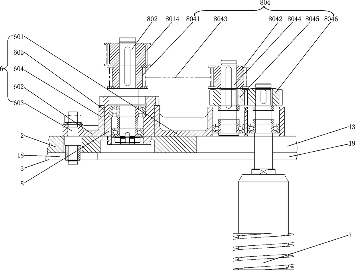
[0021] Such as figure 1 , figure 2 , image 3 As shown, the cup feeding mechanism of this cup printing machine, including the frame ( figure 1not shown in), supporting plate 2, turbine 3, worm 4, four fixed shafts 5, four swing arms 6, four screw rods 7, and a driving mechanism 8 capable of driving two adjacent screw rods 7 to rotate in opposite directions, swing arm 6 Including the long arm 601, the short arm 602 and the roller 603, the short arm 602 and the long arm 601 are connected at the connecting part 604 to form an L-shaped structure (the short arm 602, the long arm 601 and the connecting part 604 generally adopt an integrated structure) , a shaft hole 605 is provided at the connecting portion 604 of the short arm 602 and the long arm 601, and the connecting end of the roller 603 is installed at the end of the short arm 6...


PUM


Abstract

The invention discloses a cup feeding mechanism of a cup printing machine. The cup feeding mechanism of the cup printing machine comprises a machine frame, a supporting plate, a turbine, a worm, fourfixed shafts, four swing arms, four screws and a driving mechanism capable of driving every two adjacent screws to rotate in the opposite direction. The four points on the edge of an opening of a cupare subjected to synchronous transmission though screw grooves of the four screws, and the cup can be more stably and accurately connected on a cup mold in a sleeving mode, so that the alignment of the cup with a printing device is more accurate; linear wire guiding grooves and curved guiding grooves which cross each other are arranged on the turbine and supporting plate to locate the movement track of a roller shaft, the turbine pushes the swing arms to swing inside and outside through the roller shaft through the adjustment of the worm, and the diameter of a circle enclosed by the four screws is adjusted and the circle is applicable to cups of different specifications; since the screws are installed at the tail ends of long arms of the swing arms, the distance between the screws and a fixed shaft is fixed and unchanged, part of the transmission connection on the long arms follows the movement of the long arms, and when the diameter of the circle enclosed by the four screws is adjusted, any structure of the driving mechanism does not need to be changed.

Description

technical field [0001] The invention relates to a printing device, in particular to a cup feeding mechanism of a cup printing machine. Background technique [0002] The cup printing machine generally needs to transfer the cup on the cup storage rack to the cup mold, suck the cup tightly through the negative pressure suction on the cup mold, and then use the cup mold as the support to print the surface of the cup. [0003] Currently, there are two main ways to transfer cups from the cup holder to the cup mold: [0004] (1) Use the cup dividing mechanism to separate the cup at the front of the cup storage rack from the whole stack of cups, and the separated cup falls on the cylindrical cup receiving guide rail (generally surrounded by four guide rods arranged in a circle), and then Cooperate with the air blowing device to blow the cup to move in the cylindrical cup guide rail with the airflow, and finally put it on the cup mold and be sucked by the cup mold. In an improvemen...

Claims


Application Information

Patent Timeline
Patent Type & Authority Applications(China)
IPC IPC(8): B65G47/74B41F17/00
CPCB41F17/00B65G47/74B65G2201/0235
Inventor 蔡健伟
Owner 广东金兴机械股份有限公司
Why Eureka
Try Eureka