
Rotor of a rotating electrical machine

A technology for rotating electrical machines and rotors, which is applied in the field of rotors of rotating electrical machines, and can solve problems such as demagnetization of permanent magnets 113, and achieve the effect of suppressing demagnetization

Active Publication Date: 2016-11-16
HONDA MOTOR CO LTD
View PDF5 Cites 0 Cited by
  • Summary
  • Abstract
  • Description
  • Claims
  • Application Information

AI Technical Summary

Problems solved by technology

As a result, the permanent magnet 113 may be demagnetized

Method used


Image

  • Rotor of a rotating electrical machine
  • Rotor of a rotating electrical machine
  • Rotor of a rotating electrical machine

Examples


no. 2 approach

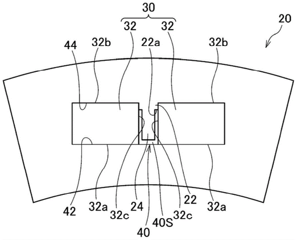
[0167] Next, a rotor 10 of a rotating electric machine according to a second embodiment of the present invention will be described. The basic structure of the rotor 10 of the present embodiment is the same as that of the first embodiment, so the description will focus on different parts, and the description of the same or corresponding parts will be omitted or simplified by assigning the same reference numerals.

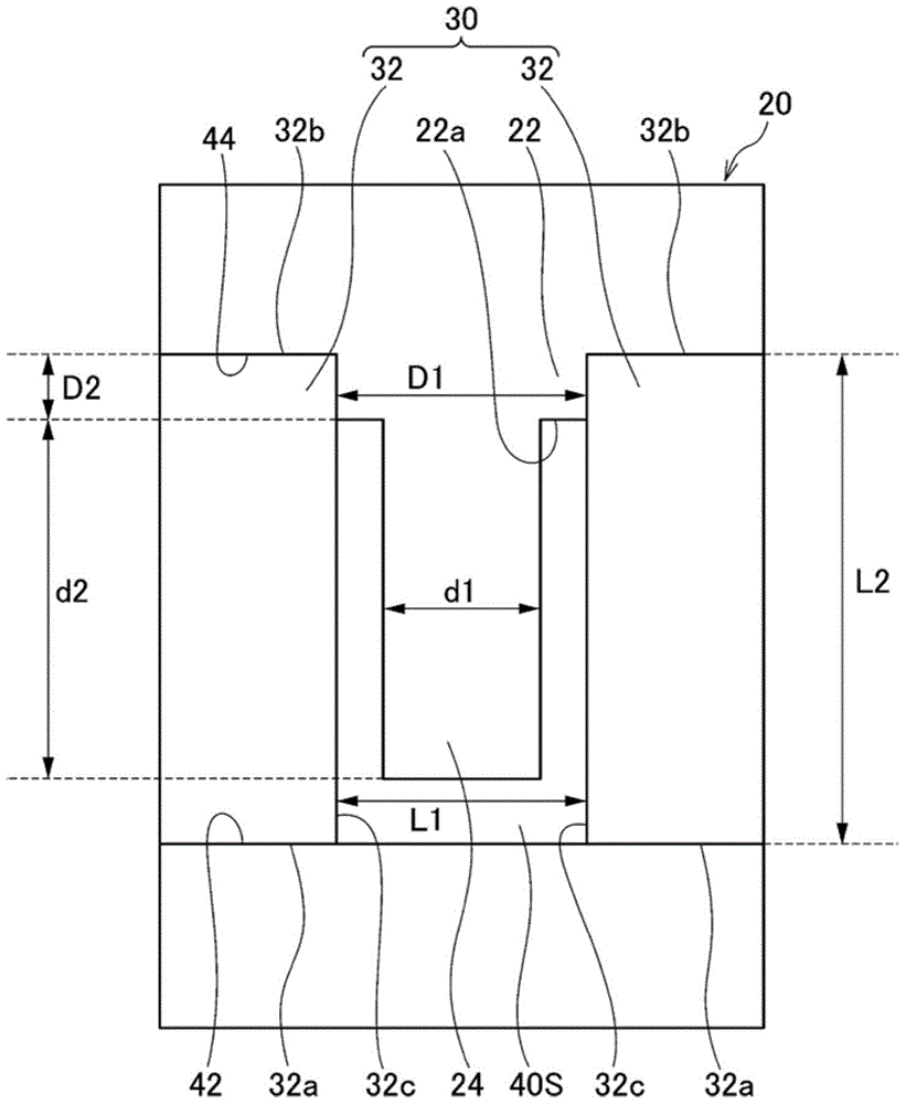
[0168] like Figure 20 and Figure 21 As shown, the rotor core 20 of the present embodiment is formed so as to extend radially inward from the outer peripheral portion 44 of the magnet insertion hole 40 between the circumferentially adjacent permanent magnet pieces 32, and the permanent magnet The retaining portion 22 on which the circumferential inner end portion 32c of the piece 32 abuts is formed so as to extend radially outward from the inner peripheral edge portion 42 of the magnet insertion hole 40 between the circumferentially adjacent permanent magnet pieces...


PUM


Abstract

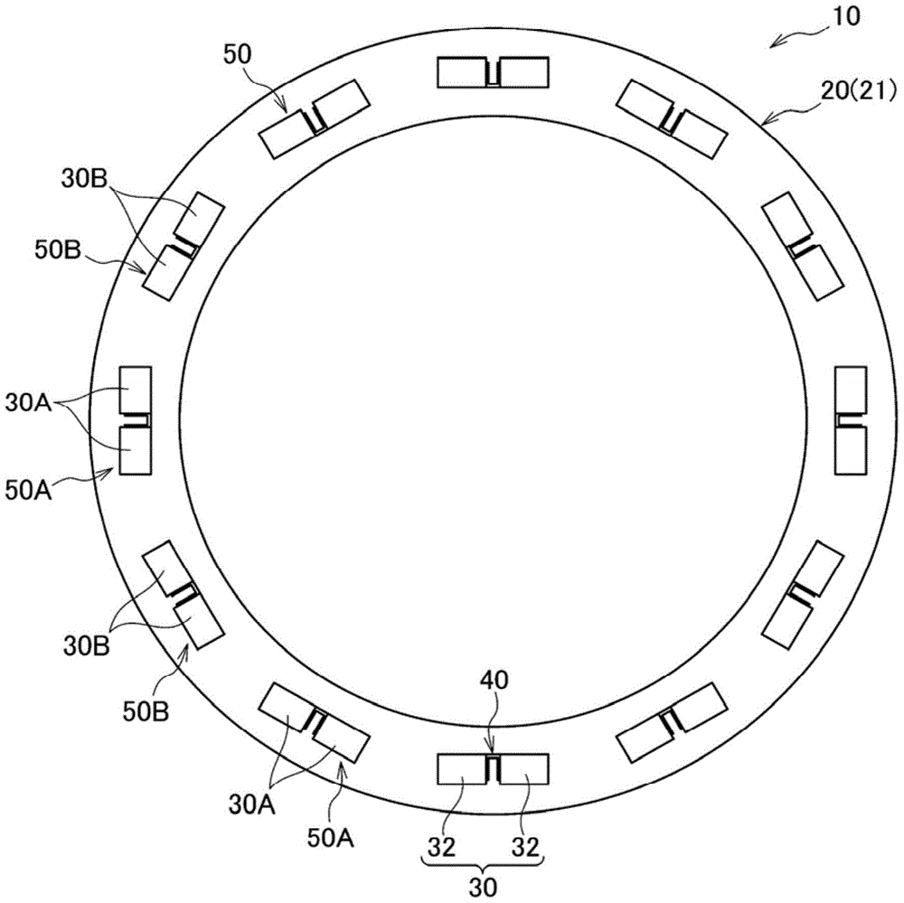
A rotor includes a rotor core and a plurality of magnetic pole parts. The rotor core has a magnet insertion hole. The magnet insertion hole includes a first peripheral edge portion and a second peripheral edge portion spaced away from the first peripheral edge portion in a radial direction of the rotor. The rotor core includes a holding part and a protrusion. The holding part extends along the radial direction from the first peripheral edge portion of the magnet insertion hole. The holding part abuts against a circumferential end portion of each of the plurality of permanent magnet pieces. The protrusion extends toward the second peripheral edge portion of the magnet insertion hole. The protrusion is spaced away in the radial direction from the second peripheral edge portion of the magnet insertion hole.

Description

technical field [0001] This invention relates to rotors for rotating electric machines. Background technique [0002] Conventionally, as a rotor used in a rotating electric machine, a rotor for a rotating electric machine in which a plurality of housing portions are provided on a rotor core formed by laminating a plurality of annular steel plates, and permanent magnets are respectively inserted into each housing portion ( For example, refer to Patent Document 1). [0003] like Figure 24 and Figure 25 As shown, the rotor 110 of the rotating electrical machine described in Patent Document 1 includes: a substantially cylindrical yoke 111 in which a permanent magnet 113 is embedded; and a rod-shaped shaft 112 provided along the central axis of the yoke 111 . The yoke 111 is provided with an accommodating portion 116 extending along the central axis, and the permanent magnet 113 is accommodated in the accommodating portion 116 and fixed by resin. [0004] In addition, the ro...

Claims


Application Information

Patent Timeline
Patent Type & Authority Patents(China)
IPC IPC(8): H02K1/27
CPCH02K1/2766H02K1/272H02K1/274H02K1/2746H02K1/2753H02K1/276
Inventor 伊达靖典白土英治壹岐友贵相马慎吾
Owner HONDA MOTOR CO LTD
Learn More