
Transfer target object separation apparatus, transferring apparatus, image formation apparatus, and transfer target object separation control method

A technology for separating devices and transfer pieces, which is applied in the fields of electric recording technology using charge patterns, equipment for electric recording technology using charge patterns, and electrography, and can solve problems such as impact and difficult separation of transfer pieces reliably

Inactive Publication Date: 2010-06-16
SEIKO EPSON CORP
View PDF12 Cites 0 Cited by
  • Summary
  • Abstract
  • Description
  • Claims
  • Application Information

AI Technical Summary

Problems solved by technology

Therefore, it is difficult to reliably perform separation of the transfer member
[0007] In addition, since air is blown toward the transfer surface side of the transfer material, the liquid developer image transferred onto the transfer material is affected by the blown air.

Method used


Image

  • Transfer target object separation apparatus, transferring apparatus, image formation apparatus, and transfer target object separation control method
  • Transfer target object separation apparatus, transferring apparatus, image formation apparatus, and transfer target object separation control method
  • Transfer target object separation apparatus, transferring apparatus, image formation apparatus, and transfer target object separation control method

Examples


Embodiment Construction

[0021] Hereinafter, preferred modes for implementing the present invention will be described with reference to the drawings.

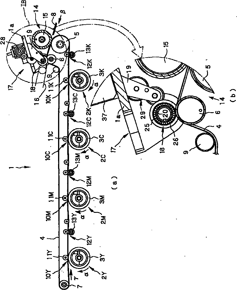
[0022] figure 1 (a) is a figure which schematically and partially shows an example of embodiment of the image forming apparatus which has the transfer material separation apparatus of this invention, figure 1 (b) is figure 1 Enlarged view of part IB of (a).

[0023] Such as figure 1 As shown in (a), the image forming apparatus 1 of this example has image forming units 2Y, 2M using liquid developers of yellow (Y), magenta (M), cyan (C), and black (K) arranged in series. , 2C, 2K. Here, among the imaging units 2Y, 2M, 2C, and 2K, 2Y indicates a yellow imaging unit, 2M indicates a magenta imaging unit, 2C indicates a cyan imaging unit, and 2K indicates a black imaging unit. In addition, also in other components, Y, M, C, and K of each color are added to the codes of the components to represent the components of each color.

[0024] Each imaging unit...


PUM


Abstract

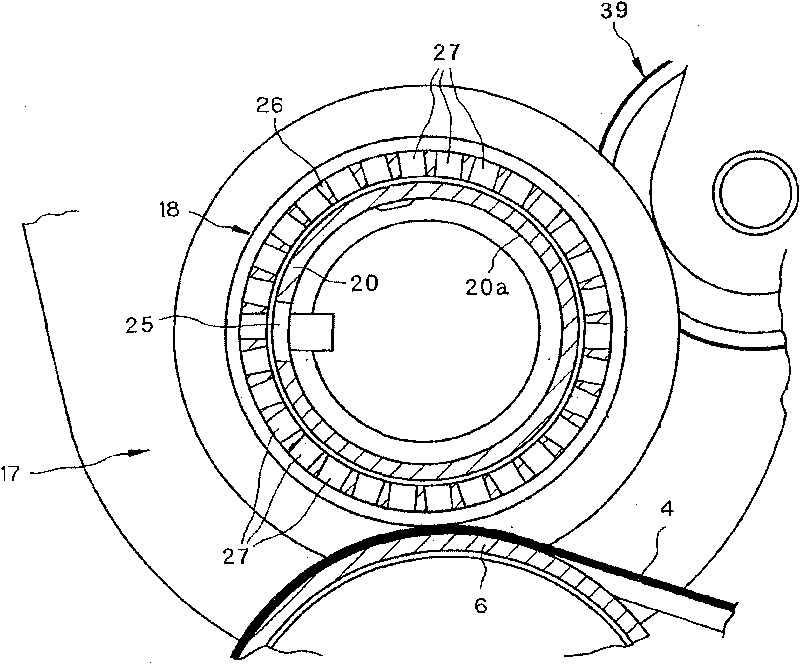
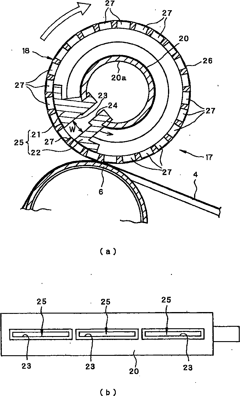
A transfer target object separation apparatus includes: a transfer target object movement member that moves a transfer target object while in contact with a first surface of the transfer target object; and a transfer target object separation suction section that sucks a second surface of the transfer target object opposite the first surface to separate the transfer target object from the transfer target object movement member. The transfer target object separation suction section includes a first cylindrical rotation member that has a suction inlet, and a second cylindrical rotation member that is fitted on the first cylindrical rotation member and has a hole through which the second surface of the transfer target object is sucked.

Description

technical field [0001] The present invention relates to the transfer of a transfer member onto which a liquid developer image has been transferred from a transfer member to an electrophotographic image forming apparatus such as a copying machine, a facsimile machine, or a printer using a liquid developer (liquid toner) image. A transfer member separation device for separating moving parts, a transfer device for transferring a liquid developer image to a transfer member, an image forming apparatus, and a transfer member separation control method. Background technique [0002] Generally, in an image forming apparatus using a liquid developer (liquid toner), a transfer member is brought into pressure contact with a transfer medium of the transfer device in a transfer device and moves together with the transfer medium, whereby the liquid developer Like transfers to transfers. In addition, the transfer material to which the liquid developer image has been transferred in the fixi...

Claims


Application Information

Patent Timeline
Patent Type & Authority Applications(China)
IPC IPC(8): G03G15/14
CPCG03G2215/00679G03G15/657
Inventor 田中伸一田中邦章
Owner SEIKO EPSON CORP
Learn More