Imaging device, imaging method, and recording medium
A camera device and image technology, applied in the field of camera device, camera method and image processing program, can solve the problem of not having angular characteristics and the like
- Summary
- Abstract
- Description
- Claims
- Application Information
AI Technical Summary
Problems solved by technology
Method used
Image
Examples
no. 1 Embodiment approach
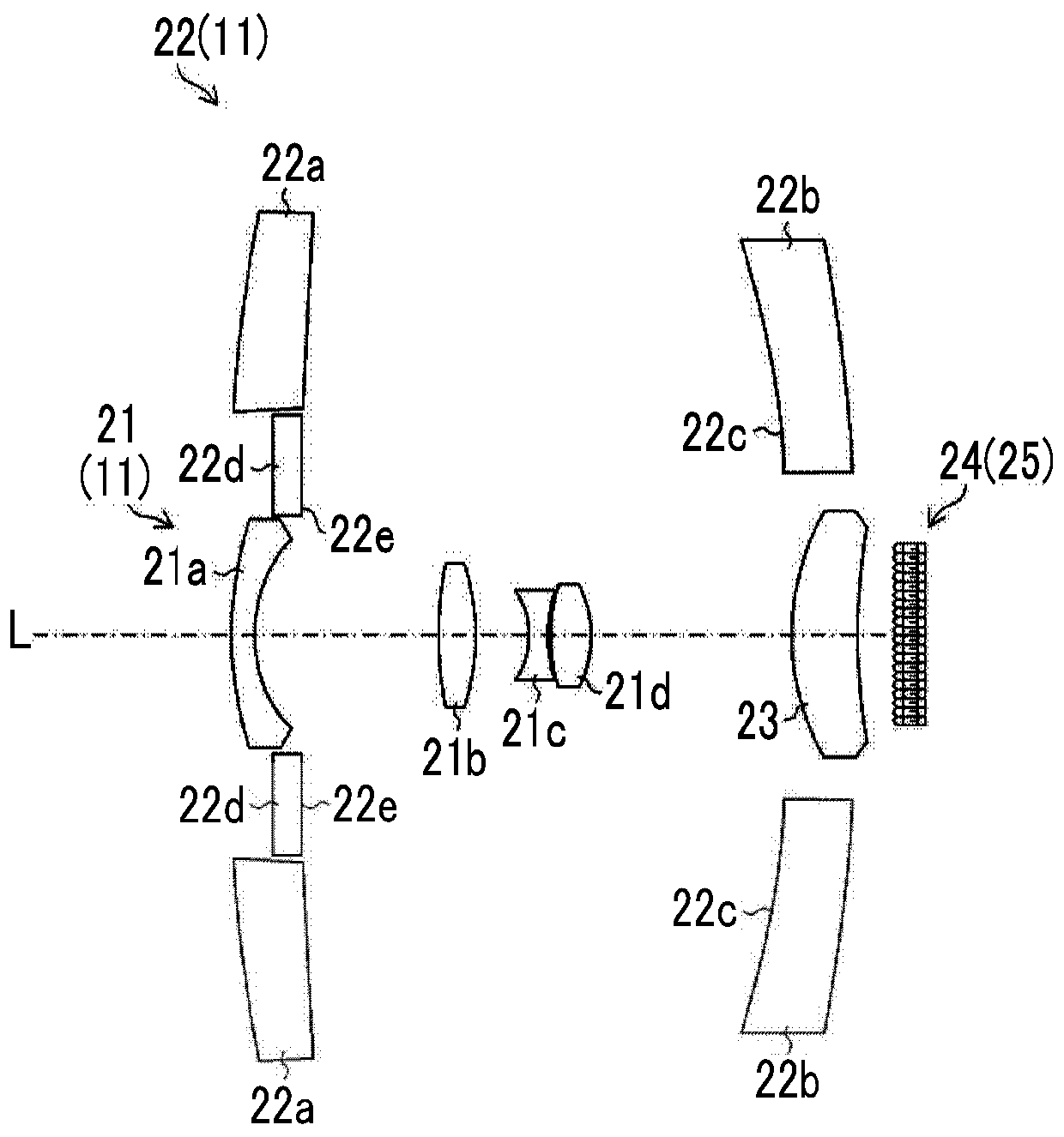
[0068] image 3 It is a diagram showing the cross-sectional structures of the complex lens 11 and the image sensor 24 according to the first embodiment.
[0069] In this example, the complex lens 11 includes a first region having a first characteristic and a second region having a second characteristic different from the first characteristic, and in this embodiment, the first optical system 21 corresponding to the first region and the second optical system 22 corresponding to the second area. In addition, the focal lengths (an example of optical characteristics) of the first optical system 21 and the second optical system 22 are different, and the optical axis L is shared. Furthermore, the first optical system 21 is a wide-angle lens, and the second optical system 22 is a telephoto lens.
[0070] image 3 The illustrated first optical system (wide-angle lens) 21 includes a first wide-angle lens 21a, a second wide-angle lens 21b, a third wide-angle lens 21c, a fourth wide-an...
no. 2 Embodiment approach
[0139] Figure 17 It is a figure for demonstrating the imaging mechanism using the complex lens 11 which concerns on 2nd Embodiment.
[0140] Figure 17 The shown complex lens 11 is composed of a circular first optical system 21 and an annular second optical system 22 arranged concentrically with respect to the first optical system 21. The light from the first optical system 21 and the second optical system The axes are shared, but the focus distance is different.
[0141] Figure 17 In , the content indicated by each reference symbol is as follows.
[0142] a1: the distance between the lens and the light receiving surface of the first optical system 21 (far focus area 60a)
[0143] a2: Distance between the lens and the light receiving surface of the second optical system 22 (near focus area 60b)
[0144] b1: distance between the lens of the first optical system 21 (far focus area 60a) and the subject
[0145] b2: distance between the lens of the second optical system 22...
no. 3 Embodiment approach
[0156] Figure 18 It is a graph showing modulation transfer function characteristics (MTF: Modulation Transfer Function) of the first optical system and the second optical system of the complex lens (not shown) according to the third embodiment.
[0157] In the complex lens according to the third embodiment, the first optical system and the second optical system have the same focal length and focusing distance, but have different MTFs, and the first optical system has Figure 18 The first MTF shown in the MTF curve a, the second optical system has Figure 18 The first 2MTF shown in the MTF curve b. In addition, the complex lens according to the third embodiment can be, for example, the appearance shape and Figure 17 The complex lens 11 shown is substantially the same.
[0158] according to Figure 18 In the MTF curve a shown, the first optical system having the first MTF has higher resolution but lower contrast than the second optical system having the second MTF. On the...
PUM
 Abstract
Description
Claims
Application Information
 - R&D
- Intellectual Property
- Life Sciences
- Materials
- Tech Scout
- Unparalleled Data Quality
- Higher Quality Content
- 60% Fewer Hallucinations
Browse by: Latest US Patents, China's latest patents, Technical Efficacy Thesaurus, Application Domain, Technology Topic, Popular Technical Reports.
© 2025 PatSnap. All rights reserved.Legal|Privacy policy|Modern Slavery Act Transparency Statement|Sitemap|About US| Contact US: help@patsnap.com


