Electric motor
A technology for a motor and a rotating device, applied in the field of motors, can solve the problems of reversal of the relationship between the size and complexity of the motor control, etc.
- Summary
- Abstract
- Description
- Claims
- Application Information
AI Technical Summary
Problems solved by technology
Method used
Image
Examples
no. 1 approach
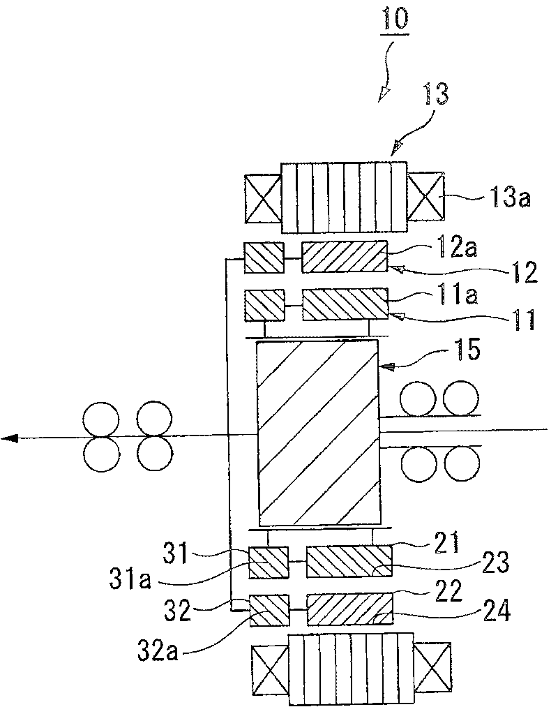
[0061] Next, a first embodiment of a motor according to the present invention will be described with reference to the drawings.
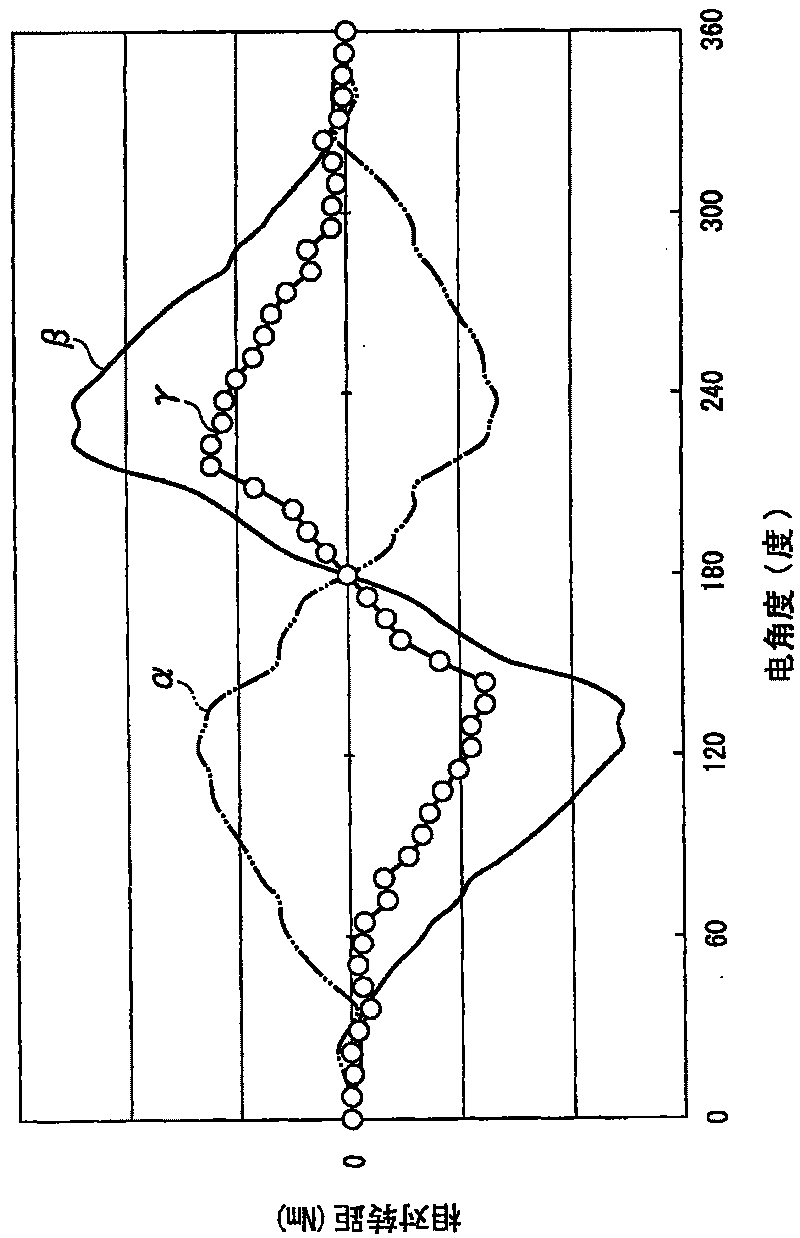
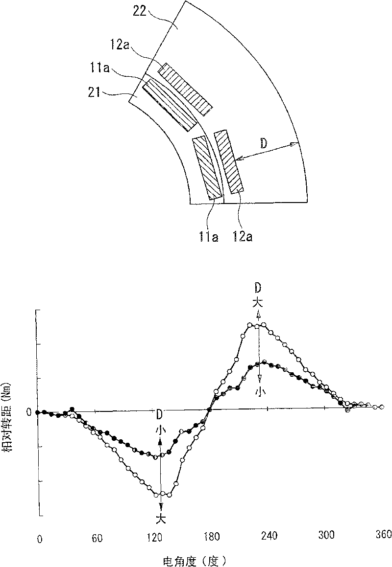
[0062] Such as figure 1 As shown, the motor 10 of this embodiment is a brushless DC motor including an inner rotor 11, an outer rotor 12, a stator 13, and a phase control device 15, wherein the inner rotor 11 and the outer rotor 12 are It has a substantially annular shape with permanent magnets 11a and 12a arranged in the circumferential direction; the stator 13 has stator windings 13a of multiple phases that generate a rotating magnetic field that rotates the inner rotor 11 and the outer rotor 12; The phase control device 15 is connected to the inner rotor 11 and the outer rotor 12 to control the relative phase between the inner rotor 11 and the outer rotor 12. The motor 10 is mounted as a drive source in, for example, a hybrid vehicle or an electric vehicle. In a vehicle, the output shaft of the electric motor 10 is connected to the input shaft ...
no. 2 approach
[0133] Below, refer to Figure 6 ~ Figure 10 A motor according to a second embodiment of the present invention will be described.
[0134] The motor 10 of the present embodiment is as Figure 6 The illustrated internal gear type brushless motor in which the rotor assembly 103 is disposed on the inner peripheral side of the annular stator 102 is used as a driving source for hybrid vehicles, electric vehicles, and the like, for example. The stator 102 has a multi-phase stator winding 102a, and the rotor assembly 103 has a rotating shaft 104 at the shaft center. When used as a vehicle driving source, the rotational force of the electric motor 101 is transmitted to drive wheels (not shown) of wheels through a transmission (not shown). At this time, when the electric motor 101 functions as a generator when the vehicle decelerates, it may be recovered as regenerative energy in the battery. In addition, in a hybrid vehicle, the rotating shaft 104 of the electric motor 101 is furth...
no. 3 approach
[0161] Figure 11 is the third embodiment of the present invention, compared to the above-mentioned second embodiment Figure 7 or Figure 8 Partial cross-sectional side view. The present embodiment will be described below, but the same parts as those in the above-mentioned second embodiment are given the same reference numerals and a part of overlapping description is omitted.
[0162] The arrangement of the motor 201 stator (not shown) and the rotor assembly 103 and the structure of the rotating mechanism 111 of this embodiment are the same as those of the second embodiment, but the structure of the outer rotor 105 is the same as that of the outer rotor of the second embodiment. different.
[0163] That is, the outer peripheral side rotor 105 of this electric motor 201 is not a rotor in which two types of rotor layers having different cross-sectional structures are joined together like the outer peripheral side rotor 105 of the above-mentioned second embodiment, and the s...
PUM
 Abstract
Description
Claims
Application Information
 - R&D
- Intellectual Property
- Life Sciences
- Materials
- Tech Scout
- Unparalleled Data Quality
- Higher Quality Content
- 60% Fewer Hallucinations
Browse by: Latest US Patents, China's latest patents, Technical Efficacy Thesaurus, Application Domain, Technology Topic, Popular Technical Reports.
© 2025 PatSnap. All rights reserved.Legal|Privacy policy|Modern Slavery Act Transparency Statement|Sitemap|About US| Contact US: help@patsnap.com


