RFID chip and antenna with improved range

Inactive Publication Date: 2007-05-03
MAGNEX
View PDF11 Cites 17 Cited by
  • Summary
  • Abstract
  • Description
  • Claims
  • Application Information

AI Technical Summary

Benefits of technology

[0012] The invention comprises a method and system for providing a “coil-on-a-chip” R

Problems solved by technology

Many more applications of this technology are theoretically possible, but practical implementations have been limited in the past by size and cost constraints.
While the process of constructing ID tag 10 appears simple and staightforward, in practice the process is actually quite difficult to perform with a high degree of repeatable accuracy.
As the physical size of the rfid chip is reduced, these difficulties in assembling a properly functioning ID tag, and the assembly cost, increase accordingly.
THis “coil-on-a-chip” approach eliminates the costly bonding step and the difficulites associated therewith. bonding of discrete components in the ID tag assembly process, it introduces a severe limitation on the effective operating range of an ID tag fabricated according to this techniqu

Method used


Image

  • RFID chip and antenna with improved range
  • RFID chip and antenna with improved range
  • RFID chip and antenna with improved range

Examples


Embodiment Construction

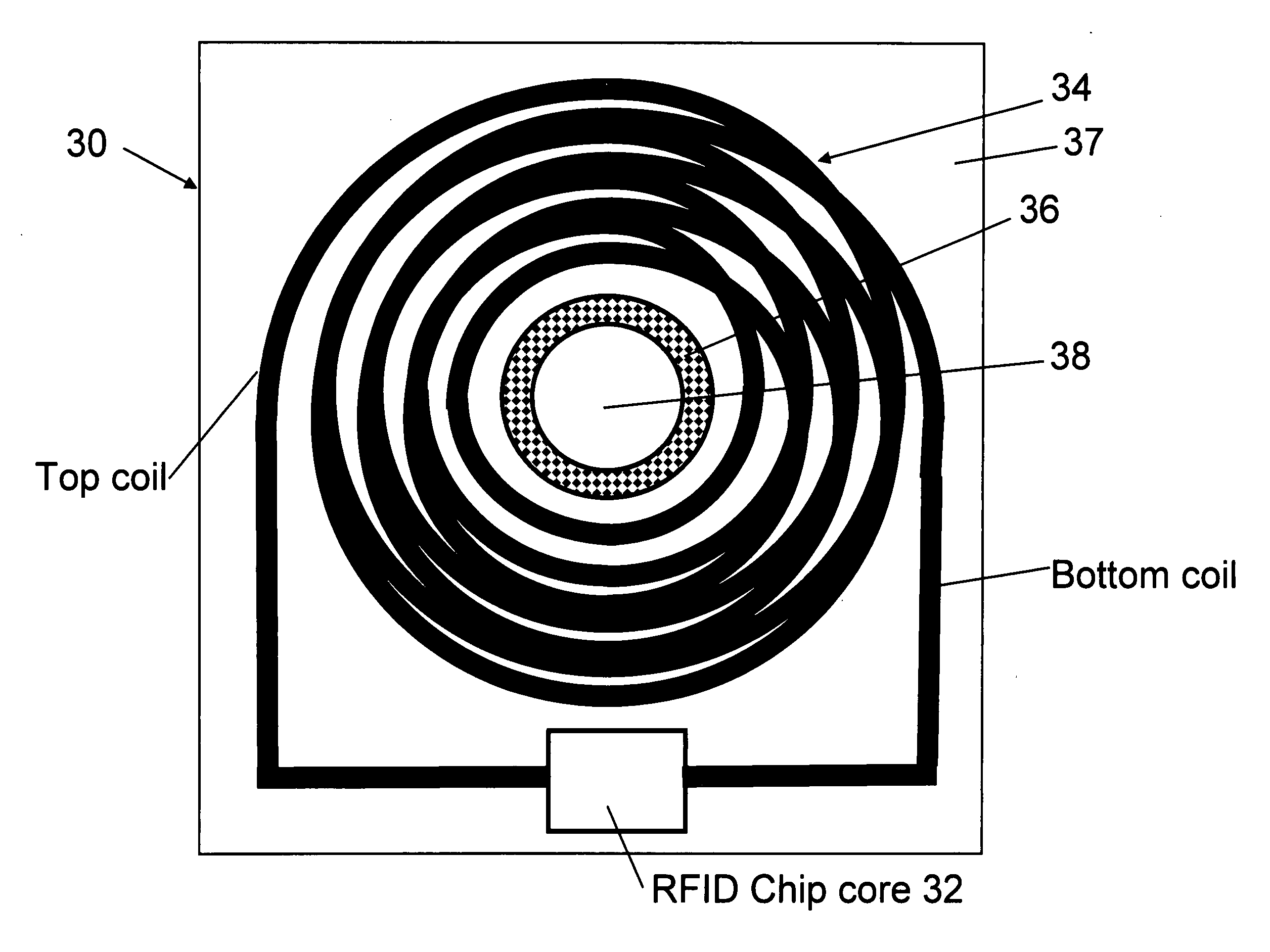
[0026] Turning now to the drawings, FIG. 3 is a top plan view of a preferred embodiment of the invention, and FIG. 4 is a sectional view taken along lines 4-4 of FIG. 3 illustrating the multiple coil turns and multiple coil layers, and the magnetically permeable layer of the antenna of the preferred embodiment. As seen in these FIGS., an RFID tag 30 comprises an rfid chip 32 and a multiple layer, multiple turn antenna coil 34 having a centrally located thin film core 36 fabricated from a material having relatively high magnetic permeability. Rfid chip 32, coil 34, and core 36 are all carried by a substrate 37. Rfid chip 32 has a major body plane, defined as the plane parallel to the major support surface of substrate 37. Multiple layer, multiple turn antenna coil 34 has a central axis of revolution 38 which is oriented at an acute angle, preferably about 90 degrees, with respect to the major body plane of rfid chip 32.

[0027] As best seen in FIG. 4, thin film core 36 is formed as an...


PUM


Abstract

A “coil-on-a-chip” RFID tag having an rfid integrated circuit and an antenna contemporaneously formed on a substrate. The antenna is a helical multiple layer, multi-turn coil having an axis of revolution oriented at an acute angle, preferably ninety degrees, with respect to the major body plane of the rfid integrated circuit. The coil has a central opening with an annular core of magnetically permeable material. The RFID tag has an increased operating range over known ID tags.

Description

BACKGROUND OF THE INVENTION [0001] This invention relates to the field of rfid (radio frequency identification) chip and antenna technology. More particularly, this invention relates to an rfid chip and antenna having an improved range of communication with an associated r.f. interrogation / reading device [0002] A typical rfid chip and antenna are usually both incorporated into an ID tag, such as that shown and described in U.S. Pat. No. 6,154,137 issued Nov. 28, 2000, the disclosure of which is hereby incorporated by reference. Generally, an ID tag has the antenna and the rfid chip mounted on or encapsulated in a thin substrate, such as a polyethylene terephthalate (PET) substrate as disclosed in U.S. Pat. No. 6,373,708 B1 issued Apr. 16, 2002, the disclosure of which is hereby incorporated by reference. The antenna is usually a small loop antenna or a dipole antenna, and must be ohmically connected to the rfid chip. The usual loop antenna is a multi-turn planar ohmic conductor form...

Claims


Application Information

Patent Timeline
IPC IPC(8): G06K19/06
CPCG06K19/07749G06K19/07756G06K19/07767
Inventor ZHU, SHENGBOHUANG, SU SHIONG
Owner MAGNEX
Why Eureka
Try Eureka