Image blur correction camera and method for controlling of image blur correction

Inactive Publication Date: 2006-12-21
NIKON CORP
View PDF4 Cites 14 Cited by
  • Summary
  • Abstract
  • Description
  • Claims
  • Application Information

AI Technical Summary

Benefits of technology

[0008] The object of the present invention is to provide an image blur correction camera that can set a blur correction operation to optimum co

Problems solved by technology

If the camera is held in the hands, there is likely to be image blur due to vibration of the hands.
Also, in the case where a picture is taken using a non-ocular viewfinder, it is common for the photographer to hold the camera out at arm's length and camera shaking is then quite significant.
Therefore, for example, if a blur correction operation is set in corre

Method used


Image

  • Image blur correction camera and method for controlling of image blur correction
  • Image blur correction camera and method for controlling of image blur correction
  • Image blur correction camera and method for controlling of image blur correction

Examples


Example

[0045] A blur correction camera of a first embodiment of the present invention will now be described in detail with reference to FIG. 1 to FIG. 3. In the first embodiment, description will be given for the case of applying the present invention to a digital camera carrying out mainly still photography.

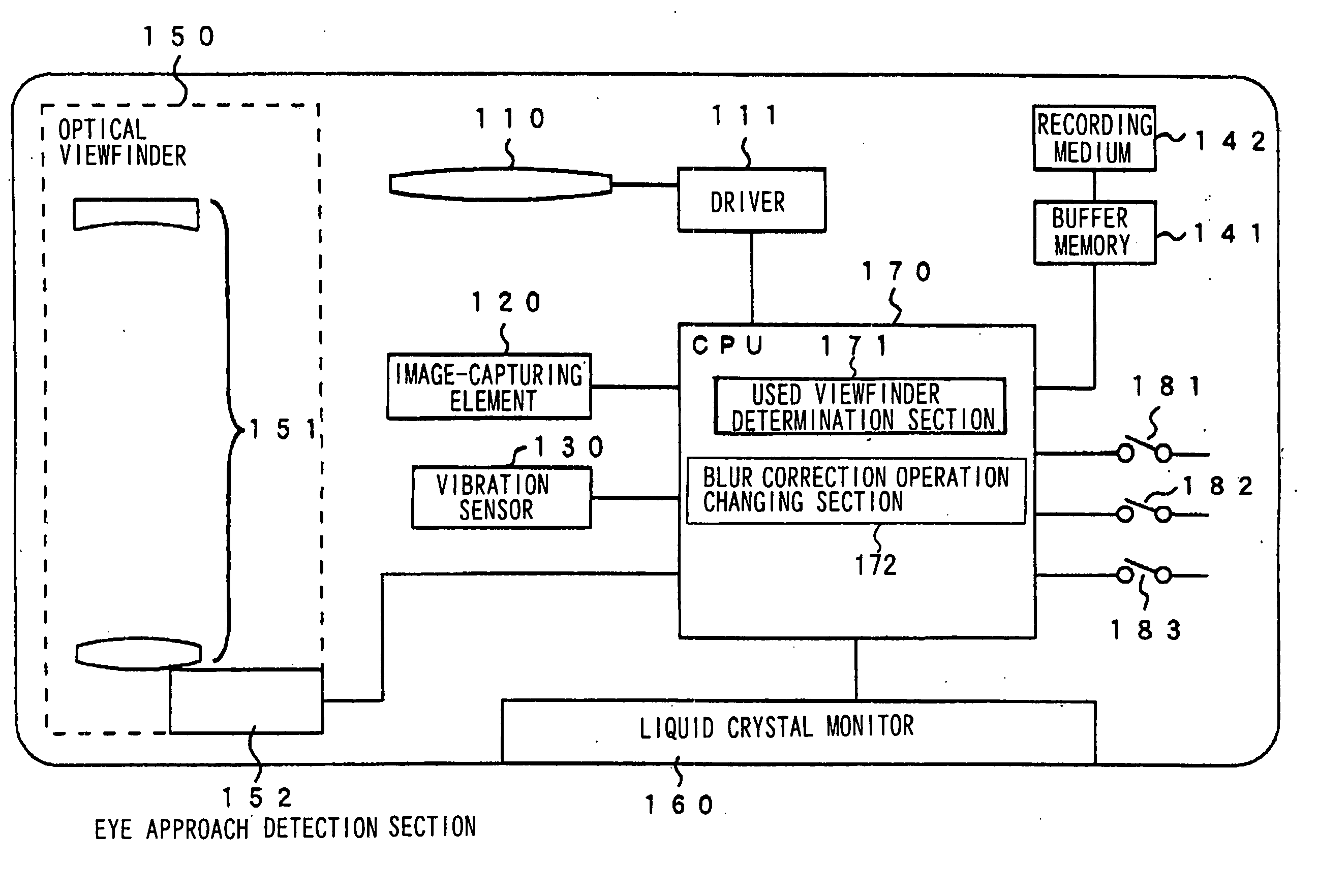
[0046]FIG. 1 is a block diagram showing the outline of a blur correction camera of the first embodiment of the present invention. As shown in FIG. 1, the blur correction camera of the first embodiment comprises a blur correction lens 110, a driver 111, an image-capturing element 120, a vibration detection sensor 130, a storage section 141, a recording medium 142, an optical viewfinder 150 constituted of a viewfinder optical system 151 and an eye-approach detection section 152, a liquid crystal monitor 160 and a CPU 170. The blur correction camera also comprises a monitor switch 181, a half-way push down switch 182 and an all-the-way push down switch 183.

[0047] The blur correction len...

Example

Second Embodiment

[0080] A blur correction camera of a second embodiment is constructed so that the extent of movement of the blur correction lens 110 becomes large compared to the first embodiment, and the range over which blur correction can be performed is increased. The outline of a blur correction camera of the second embodiment is the same as the first embodiment shown in FIG. 1. Description here will mainly focus on points of difference from the first embodiment.

[0081] The blur correction lens 110 is part of a photographing optical system (not shown), as in the first embodiment, and is constituted of a single lens or a plurality of lenses that are capable of movement in a plane substantially orthogonal to the optical axis. The blur correction lens 110 of the second embodiment is constructed so as to be capable of movement over a wider range than that in the first embodiment. In this way, it is possible to carry out correction of image blur caused by comparatively large hand ...

Example

Third Embodiment

[0102] In the third embodiment, a description will be given of the case where the blur correction camera of the present invention is applied to a video camera for taking moving pictures.

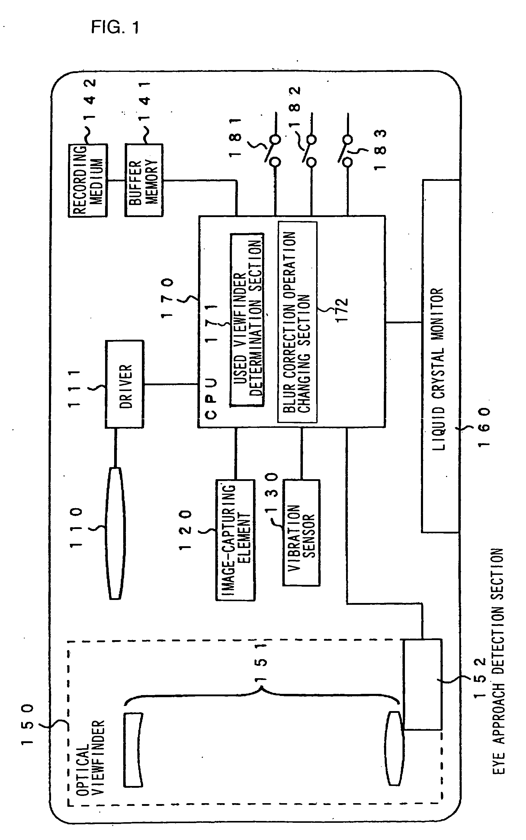
[0103]FIG. 6 is a block diagram showing the outline of a blur correction camera of the third embodiment of the present invention. As shown in FIG. 6, the CPU 170 of the blur correction camera of the third embodiment also executes a control program that functions as an electronic blur correction section 173. A recording start switch 184 is provided instead of the half-way push down switch 182 and the all-the-way push down switch 183. Sections that are common to the first embodiment have the same reference numerals attached thereto, and their descriptions are omitted.

[0104] The electronic blur correction section 173 performs image blur correction for an image to be recorded by outputting an image formed on the image-capturing element 120 with a displacement in a direction opposite to...


PUM


Abstract

A used viewfinder determination section determines whether an optical viewfinder is being used or if a liquid crystal monitor is being used, based upon signals from an eye approach detection section. A blur correction operation changing section changes a blur correction operation by a blur correction lens in accordance with determination results from the used viewfinder determination section. When it is determined that the optical viewfinder is not being used, a blur correction operation using the blur correction lens is not carried out.

Description

[0001] This is a Continuation of U.S. patent application Ser. No. 09 / 987,733 filed on Nov. 15, 2001, which is hereby incorporated by reference in its entirety. This application claims priority to Japanese Patent Application No. 2000-350715 filed Nov. 17, 2000, which is hereby incorporated by reference in its entirety.BACKGROUND OF THE INVENTION [0002] 1. Field of the Invention [0003] The present invention relates to an image blur correction camera and a method for controlling of image blur correction for correcting an image blur caused by hand vibration, with an ocular viewfinder and a non-ocular viewfinder. [0004] 2. Description of Related Art [0005] In digital still cameras and digital video cameras, it is common practice to provide an ocular viewfinder that a photographer peers into with the eye brought into close contact, in order to confirm a photographing range, etc., as well as a non-ocular viewfinder that uses a liquid crystal display or the like, in order to confirm the pho...

Claims


Application Information

Patent Timeline
IPC IPC(8): H04N5/228G03B13/02G03B5/00G03B19/02H04N5/232
CPCH04N5/23248H04N5/23258H04N5/23293H04N5/23287H04N5/23264H04N23/68H04N23/682H04N23/6812H04N23/635H04N23/687
Inventor TAKEMOTO, MASAMITOMITA, HIROYUKIKUSAKA, YOSUKE
Owner NIKON CORP
Why Eureka
Try Eureka