Catalytic Secondary Reforming Process and Reactor for Said Process

Active Publication Date: 2007-11-15
CASALE SA
View PDF3 Cites 2 Cited by
  • Summary
  • Abstract
  • Description
  • Claims
  • Application Information

AI Technical Summary

Benefits of technology

[0010] The technical problem underlying the present invention is that of providing a catalytic secondary reforming process of the type considered, in which a substantially uniform temperature distribution or, at mos

Problems solved by technology

As regards to secondary reforming processes of the prior art, it has constantly been noted at the entry of the catalytic bed that there is substantial non-uniformity of temperature distribution, quantifiable in ΔT, between two different zones of the surface of said

Method used


Image

  • Catalytic Secondary Reforming Process and Reactor for Said Process
  • Catalytic Secondary Reforming Process and Reactor for Said Process
  • Catalytic Secondary Reforming Process and Reactor for Said Process

Examples


Example

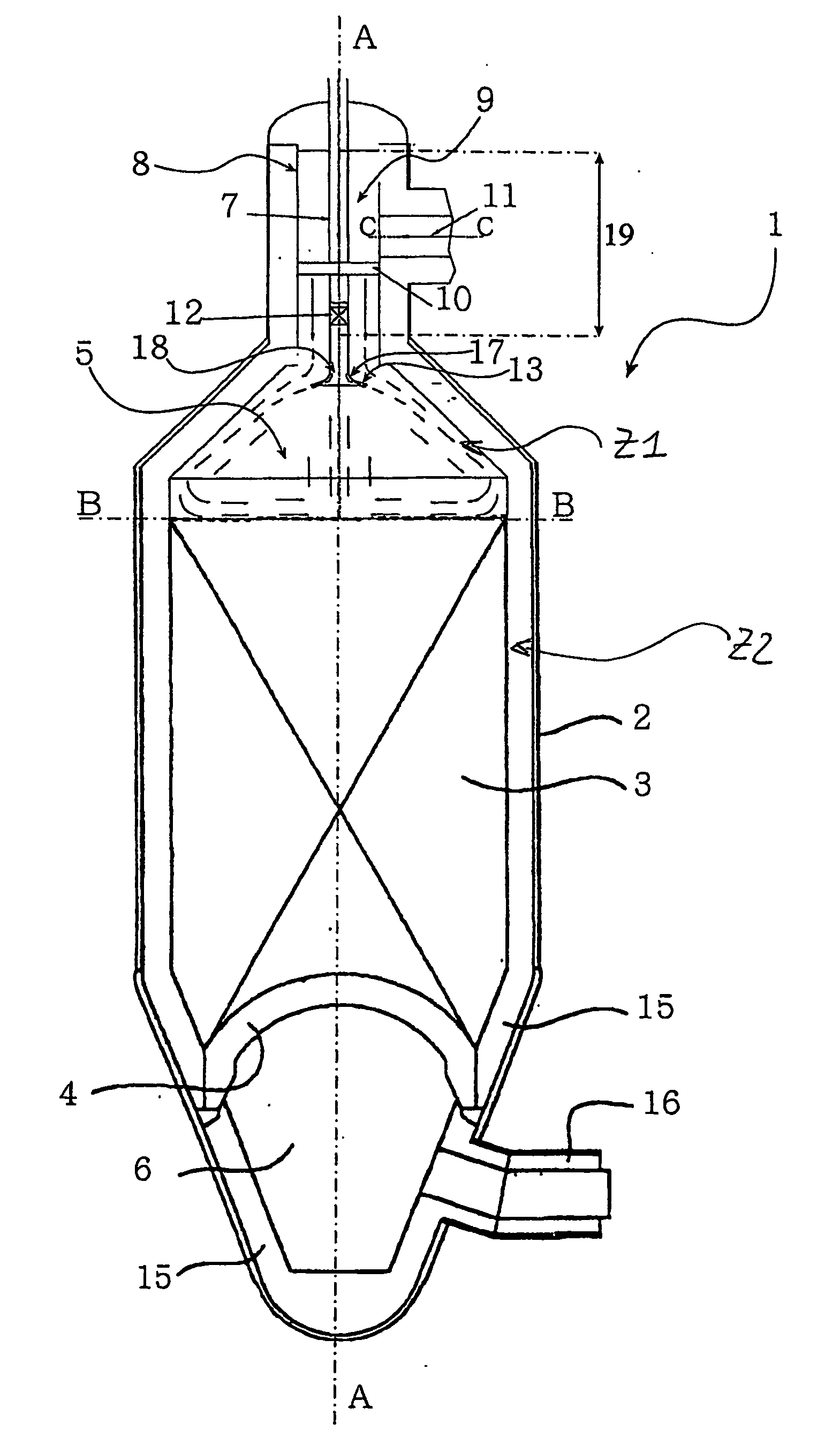
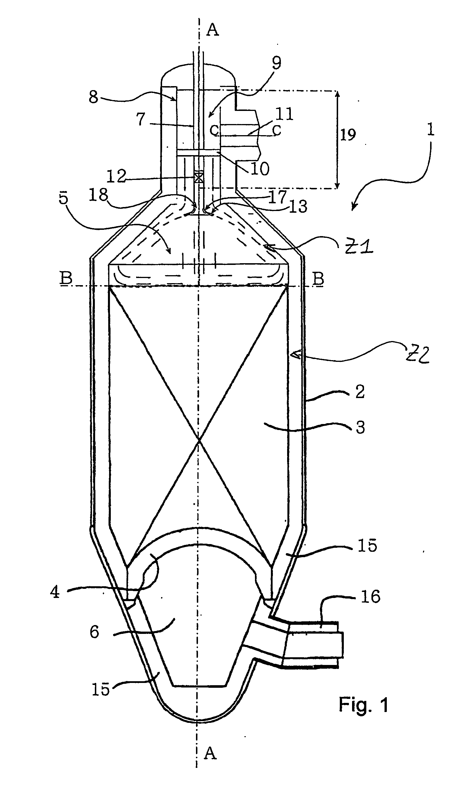
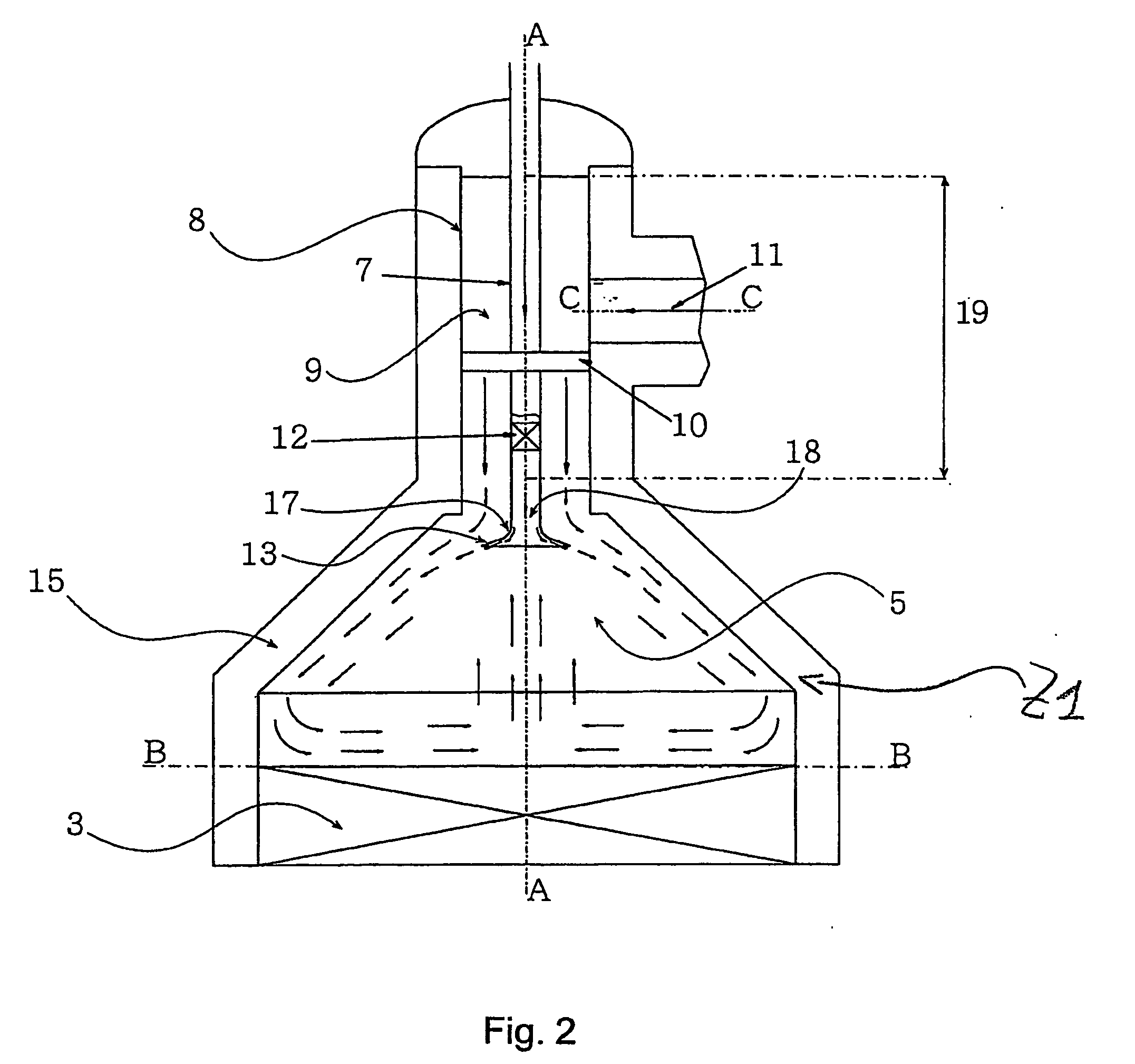
[0021] With reference to FIG. 1, a reactor for carrying out the catalytic secondary reforming process of the present invention is globally indicated with 1.

[0022] Such reactor comprises a substantially cylindrical shell 2, with a vertical axis A-A, and having an inner wall coated with refractory material resistant to high temperatures, generally indicated with 15 in FIG. 1. In said reactor a first zone Z1 and a second zone Z2, on top of one another and in fluid communication with each other, are defined. A catalytic bed 3, the upper surface or “free surface” of which constitutes a plane B of separation between said zones, is supported, in a per se known way, in the lower zone Z2.

[0023] At the upper and lower ends, having frusto-conical shape, of the shell 2 are respectively defined a reaction chamber 5, in the first zone Z1, defined at the bottom by said plane B (upper surface of the catalytic bed 3), and a collection chamber 6 of the reaction products in fluid communication with ...


PUM

PropertyMeasurementUnit
Angleaaaaaaaaaa
Lengthaaaaaaaaaa
Diameteraaaaaaaaaa

Abstract

A catalytic secondary reforming process, for the production of synthesis gas, comprises the successive steps of: feeding a first gas flow comprising hydrocarbons and a second gas flow comprising oxygen into a reforming reactor, at least one of such gas flows being fed into the reactor in a predetermined feed direction substantially parallel, preferably coaxial, to a longitudinal axis of the reactor, mixing the gas flows in the reactor, with substantially simultaneous oxidation of the hydrocarbons of the first gas flow by the oxygen of the second flow.

Description

FIELD OF APPLICATION [0001] The present invention refers, in its most general aspect, to a catalytic secondary reforming process, for the production of synthesis gas, of the type comprising the successive steps of: [0002] feeding a first gas flow comprising hydrocarbons and a second gas flow comprising oxygen into a reforming reactor, at least one of said gas flows being fed into said reactor in a predetermined feed direction substantially parallel, preferably coaxial, to a longitudinal axis of said reactor, [0003] mixing said gas flows in said reactor, with substantially simultaneous oxidation of the hydrocarbons of said first gas flow by the oxygen of said second gas flow. [0004] In the rest of the description and in the subsequent claims, with the term “hydrocarbons” we generically mean to identify a hydrocarbon or mixtures of hydrocarbons that are saturated and / or unsaturated, light and / or heavy (for example C1-C6); with “gas flow comprising hydrocarbons” we mean to identify pre...

Claims


Application Information

Patent Timeline
IPC IPC(8): C01B3/38B01F23/10B01J4/00B01J8/02B01J8/04B01J19/26
CPCB01F5/0451B01F2005/0017B01J8/025B01J8/0278B01J8/0492B01J2208/00849C01B2203/82C01B2203/0244C01B2203/0844C01B2203/1235C01B2203/1276C01B2203/142C01B3/382B01F2025/913B01F25/3131
Inventor ZANICHELLI, LUCA
Owner CASALE SA
Why Eureka
Try Eureka