Injection device for combustion chambers of liquid-fueled rocket engines

a technology of injection device and combustion chamber, which is applied in the direction of propulsive elements, cosmonautic components, cosmonautic parts, etc., can solve the problems of hot gas corrosion, fuel strand formation, and inability to meet the requirements of combustion chamber, etc., to achieve stable operation, low hydraulic pressure loss, and uniform temperature and power distribution

Inactive Publication Date: 2007-03-29
EADS SPACE TRANSPORTATION
View PDF6 Cites 0 Cited by
  • Summary
  • Abstract
  • Description
  • Claims
  • Application Information

AI Technical Summary

Benefits of technology

[0010] The present invention addresses these drawbacks with an injection device for combustion chambers of liquid-fueled rocket engines that, with low hydraulic pressure loss, provides a stable operation and a uniform temperature and power distribution over a wide operating range.

Problems solved by technology

These types of injection heads have the disadvantage that fuel strands can form in the combustion chamber, in which strands either a rich combustion prevails through an excess of fuel or a lean combustion prevails through an excess of oxidizer.
Such strand formation impairs the burn-out degree (i.e., the efficiency factor of the combustion).
Lean strands can lead to hot-gas corrosion or to localized excessive temperatures (e.g., “hot spots” on the combustion chamber wall) and possibly result in the destruction of the combustion chamber.
Strands with fuel excess, if it is a thermally degradable fuel, can lead to local pressure peaks that can cause high-frequency combustion instabilities.
Such known injection devices for combustion chambers of liquid-fueled rocket engines have different disadvantages due to their respective systems.
Turbulent injection systems necessitate a high injection head pressure loss.
Furthermore, it is disadvantageous when the fuel components mix on the wall of the combustion chamber, leading to a high thermal load of the combustion chamber wall.
Showerhead injection devices require a large combustion chamber and have a low output and a poor thermal stability.

Method used


Image

  • Injection device for combustion chambers of liquid-fueled rocket engines
  • Injection device for combustion chambers of liquid-fueled rocket engines

Examples


Embodiment Construction

[0037] The particulars shown herein are by way of example and for purposes of illustrative discussion of the embodiments of the present invention only and are presented in the cause of providing what is believed to be the most useful and readily understood description of the principles and conceptual aspects of the present invention. In this regard, no attempt is made to show structural details of the present invention in more detail than is necessary for the fundamental understanding of the present invention, the description taken with the drawings making apparent to those skilled in the art how the several forms of the present invention may be embodied in practice.

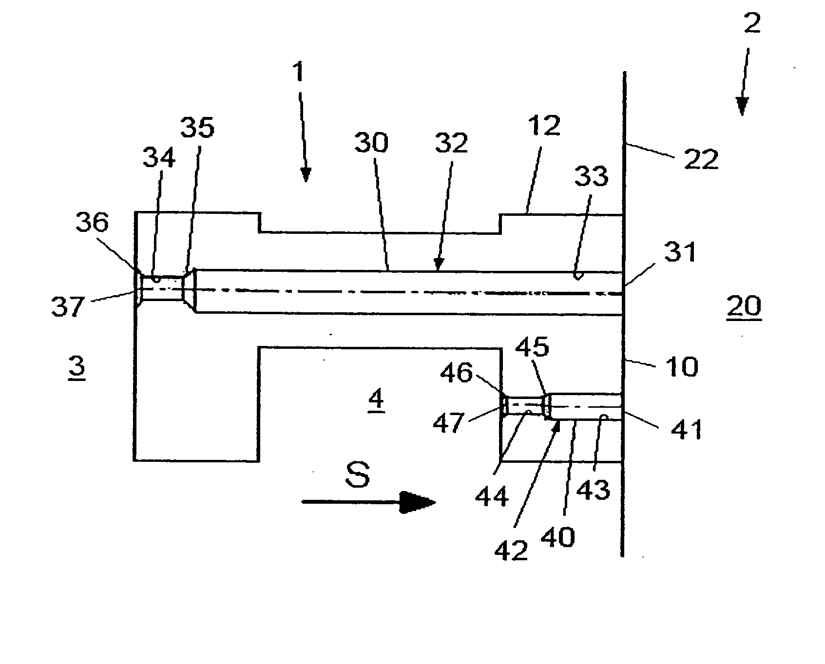
[0038]FIG. 1 shows a first embodiment of an injection device 1 according to the invention for a combustion chamber 2 of a liquid-fueled rocket engine. The combustion chamber 2 has a combustion space 20 with a wall 22. A part of the wall 22 is formed by an injection plate 10 of the injection device 1. The injection plate...


PUM


Abstract

An injection device including at least one injection plate adjacent a combustion space of a combustion chamber, and at least one first injection nozzle including a first entry bore having a first discharge into the combustion chamber, and a first orifice bore, having a cross-sectional dimension less than or equal to the first entry bore, coaxially arranged with the first entry bore and remote from the first discharge. At least one second injection nozzle includes a second entry bore having a second discharge into the combustion chamber, and a second orifice bore, having a cross-sectional dimension less than or equal to the second entry bore, coaxially arranged with the second entry bore and remote from the second discharge. The instant abstract is neither intended to define the invention disclosed in this specification nor intended to limit the scope of the invention in any way.

Description

CROSS-REFERENCE TO RELATED APPLICATIONS [0001] The present application claims priority under 35 U.S.C. §119 of German Patent Application No. 10 2005 024 608.7, filed on May 25, 2005, the disclosure of which is expressly incorporated by reference herein in its entirety. BACKGROUND OF THE INVENTION [0002] 1. Field of the Invention [0003] The invention relates to an injection device for combustion chambers of liquid-fueled rocket engines including an injection plate adjacent to the combustion space of the combustion chamber, at least one first injection nozzle for a first fuel component, and at least one second injection nozzle for a second fuel component. [0004] 2. Discussion of Background Information [0005] The function of an injection device of a rocket engine is to guarantee a complete combustion of the fuel with low combustion-chamber volume by good mixture preparation, to ensure a homogeneous combustion gas mixture, a high combustion stability and the lowest possible injection pr...

Claims


Application Information

Patent Timeline
Patent Type & Authority Applications(United States)
IPC IPC(8): F02K9/52
CPCF02K9/52
Inventor GOTZIG, ULRICHMAY, DIETER
Owner EADS SPACE TRANSPORTATION
Why Eureka
Try Eureka