Pump light stripper for optical fiber laser

A fiber laser and pump light technology, applied in the direction of lasers, laser components, phonon exciters, etc., can solve problems such as high optical power, uneven temperature distribution of strippers, and influence of temperature distribution device operation reliability, etc., to achieve The effect of uniform temperature distribution

Inactive Publication Date: 2014-03-05
广东高聚激光有限公司 +1
View PDF5 Cites 1 Cited by
  • Summary
  • Abstract
  • Description
  • Claims
  • Application Information

AI Technical Summary

Problems solved by technology

In the manufacturing process of the existing optical stripper, the new coating material will be evenly coated. The problem is that the amount of light stripped everywhere is proportional to the remaining optical power at this position, causing the first The optical power stripped by the stripping point is the most, and then decreases according to the geometric progression relationship until the power stripped by the last stripped point is much

Method used


Image

  • Pump light stripper for optical fiber laser
  • Pump light stripper for optical fiber laser
  • Pump light stripper for optical fiber laser

Examples


Example Embodiment

[0030] Example one

[0031] Such as Figure 5 The optical stripper 5'for the fiber laser shown mainly includes an optical fiber core 51', an optical fiber inner cladding layer 52', and a coating layer 53', wherein the optical fiber inner cladding layer 52' ​​covers the fiber core 51', and the coating layer 53' is coated outside the inner cladding layer 52' ​​of the optical fiber, and the refractive index of the coating layer material is higher than that of the inner cladding layer material of the optical fiber, and conventional optical gel and other materials can be used. From Figure 5 It can be seen that the coating layer 53' is divided into a piece of circular stripping points of the same size, and the stripping points are named the first stripping point, the second stripping point, and the third stripping point in sequence along the transmission direction a of the pump light. Peeling point,..., the nth peeling point.

[0032] The width of the peeling points and the number of p...

Example Embodiment

[0041] Example two

[0042] Such as Picture 9 The optical stripper 5" for the fiber laser shown mainly includes an optical fiber core 51", an optical fiber inner cladding layer 52", and a coating layer 53", wherein the optical fiber inner cladding layer 52" covers the optical fiber core 51' The coating layer 53" is coated outside the optical fiber inner cladding layer 52". The refractive index of the coating layer material is higher than that of the optical fiber inner cladding layer. Conventional optical gel and other materials can be used. From Picture 9 It can be seen that the coating layer 53" is divided into a piece of circular stripping points with equal spacing. The stripping points are named the first stripping point, the second stripping point, and the second stripping point in sequence along the transmission direction a of the pump light. Three peeling points,..., the nth peeling point.

[0043] The distance between the peeling points and the number of peeling points...


PUM


Abstract

The invention relates to a pump light stripper for an optical fiber laser. The pump light stripper for the optical fiber laser comprises an optical fiber core, an inner optical fiber wrapping layer and a coating layer, wherein the refractive index of the materials of the coating layer is higher than that of the materials of the inner optical fiber wrapping layer, annular stripping points with the same size are arranged to form the coating layer, and the intervals between the striping points become smaller sequentially in the transmission direction of pump light, or the annular stripping points are arranged at equal intervals to form the coating layer, and the widths of the stripping points become larger in sequence in the transmission direction of the pump light. According to the pump light stripper for the optical fiber laser, due to the fact that the stripping points with the same size are arranged in the mode that the intervals between the stripping point become smaller in sequence to form the coating layer or the stripping points are arranged at equal intervals in the mode that the widths of the stripping points become larger in sequence to form the coating layer, the powers of pump light stripped by the stripping points can be similar, and then even distribution of the temperature of the stripper is facilitated.

Description

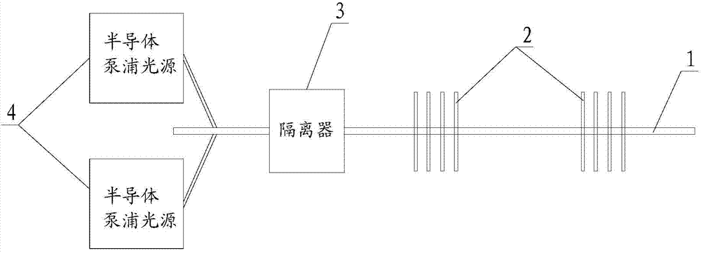
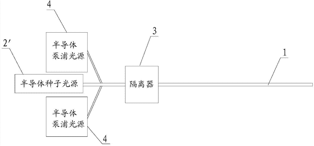
technical field [0001] The invention relates to the field of semiconductor optoelectronics, in particular to a pump light stripper for fiber lasers. Background technique [0002] Fiber lasers are widely used in industrial fields such as laser welding, cutting, drilling, surface treatment and marking because of their advantages such as high energy conversion efficiency, simple structure, low cost, and high beam quality. The main performance parameters are: output power, The beam quality, the photoelectric conversion efficiency of the overall system, the amount of pump light remaining in the fiber, etc. The active medium of a fiber laser is usually a silica glass fiber doped with the rare earth element ytterbium, which corresponds to an absorption spectrum of about 910-977 nm and an emission spectrum of about 1032-1064 nm. There are two typical structures: one is an optical fiber Resonant cavity structure, that is, a pair of DBR gratings are made in the optical fiber. The ref...

Claims


Application Information

Patent Timeline
IPC IPC(8): H01S3/042H01S3/067
Inventor 仇伯仓赵青春杜毅嵩
Owner 广东高聚激光有限公司
Why Eureka
Try Eureka