Hybrid heating apparatus applicable to the moving granular bed filter

Active Publication Date: 2015-04-30
INST NUCLEAR ENERGY RES ROCAEC
View PDF15 Cites 1 Cited by
  • Summary
  • Abstract
  • Description
  • Claims
  • Application Information

AI Technical Summary

Benefits of technology

[0012]Another objective of the present invention is to provide a hybrid heating apparatus, which inserts the electric heating bars into the tank for supplying the heat sources thereto. Those electric heating bars can be arranged to make the temperature distribution in the system more uniform based on the fact that the heat is not supplied from the periphery only. Moreover, users can adjust the geometrical arrangement depending on the situation, facilitating the flexibility of the system.
[0013]Still another objective of the present invention is to provide a hybrid heating apparatus. In addition to using the direct-contact electric heating bars, the heated gas is also used and flows upwards from the bottom of the tank. This high-temperature gas can flow in the gaps among the heated granular materials and thus further improving the heating uniformity of the system. Compared with the case in which the gas without flowing, the flow phenomenon of the heated gas enhanced the convection, which reduces the convection thermal resistance Rcv. Thereby, the total thermal resistance Rt of the system is lowered and the heat transfer effect is increased. Besides, by combining the present invention with other apparatuses or systems, their exhaust gas and waste heat and can recycled and hence reducing power consumption and promoting environmental protection.
[0014]A further objective of the present invention is to provide a hybrid heating apparatus, which adopts the hot exhaust gas as the main heating source and the electrical heating system as the auxiliary one. In other words, the low power consumptio

Problems solved by technology

Nonetheless, liquid material with a high viscosity would hinder convection in the heating process.
Consequently, the thermal energy provided by the heat sources may concentrate excessively in the region close to the bottom of the heating tanks and lead to nonuniform heating.
Some materials may deteriorate due to overheating caused by heat retention.
When the heated materials are granular materials the contact areas among granules are small and nonuniform, resulting in increased thermal resistance (R), which becomes a great obstacle for heat transfer.
In addition, through stirring the granules with higher temperature can contact those not nearby initially, and thus shorten the heat transfer paths.
Nonetheless, in practice it is not easy to heat the granular materials clos

Method used


Image

  • Hybrid heating apparatus applicable to the moving granular bed filter
  • Hybrid heating apparatus applicable to the moving granular bed filter
  • Hybrid heating apparatus applicable to the moving granular bed filter

Examples


Example

[0024]In order to make the structure and characteristics as well as the effectiveness of the present invention to be further understood and recognized, the detailed description of the present invention is provided as follows along with embodiments and accompanying figures.

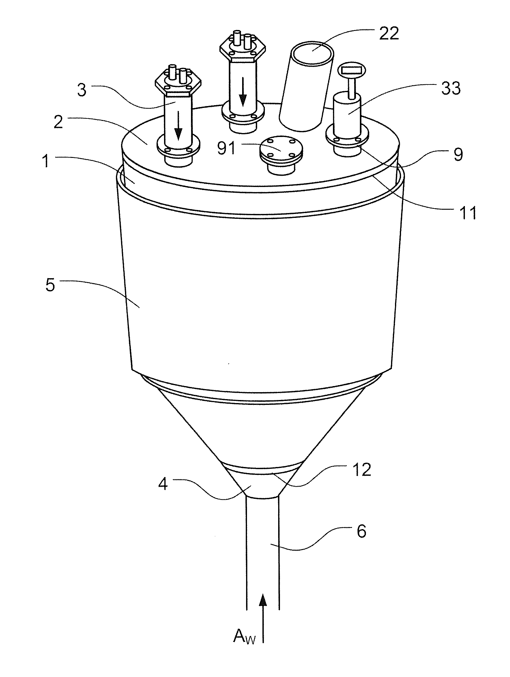
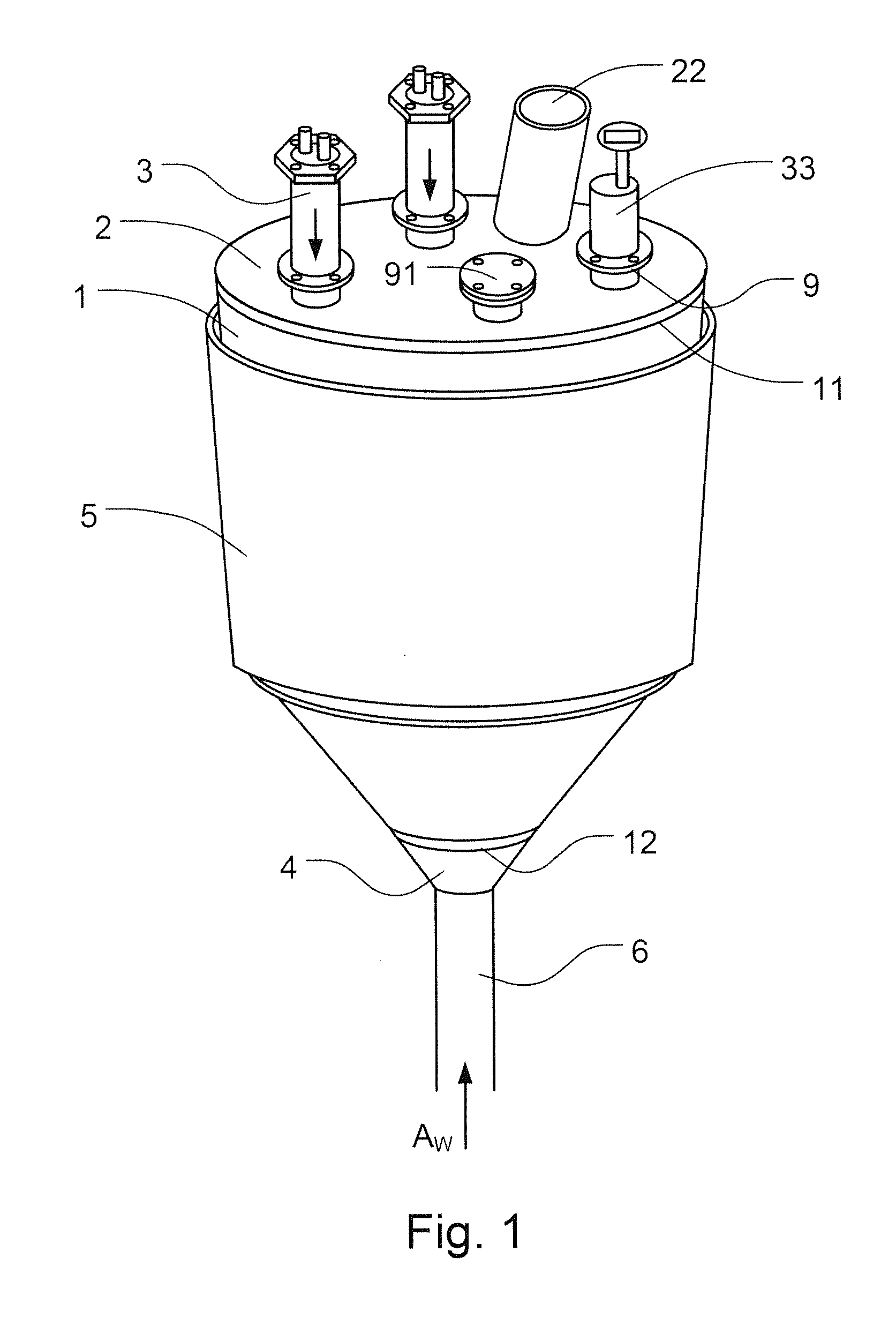
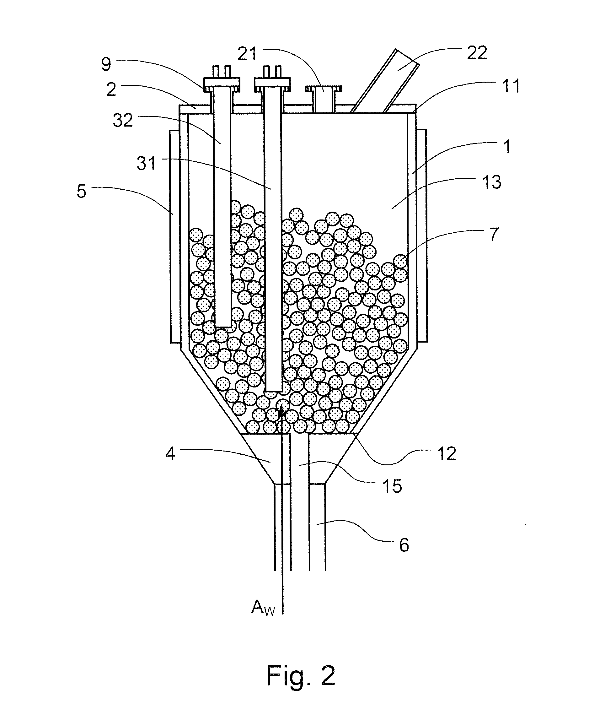
[0025]First, please refer to FIG. 1 and FIG. 2, which show structural schematic diagrams according to the present invention. As shown in the figures, the structure of the hybrid heating apparatus comprises a tank 1, a top opening part 11, a bottom opening part 12, a lid 2, a plurality of holes 21, at least an inner heating unit 3, a gas distributor 4, and an outer heating unit 5. The top and bottom opening parts 11, 12 are located on the top and bottom ends of the tank 1. Lid 2 is disposed on the top opening part 11. The plurality of holes 21 are disposed on the surface of the lid 2. In addition, the plurality of holes 21 have flanges 9, respectively, used as the connecting members with the inner heating unit 3.

[00...


PUM


Abstract

A structure of hybrid heating equipment according to the present invention is disclosed. The present invention combines a multiple of the thermal sources for heating the interior materials of the container simultaneously, and assures the materials could gain the thermal energy uniformity. Furthermore, the present invention allows users to control the level of the heating simply through adjusting the length of interior heating elements or the flow rate of the incoming gas. In addition, the present invention connect with the tubes of the hot exhaust gas to further lower the influence of the thermal resistance by coordinating the flow of the hot exhaust gas, therefore fully reflect the advantages of the conserving energy and reducing the carbon emissions by reusing the waste heat as the principal source while the electric heating devices as supplement.

Description

FIELD OF THE INVENTION[0001]The present invention relates to a heating apparatus, which is applicable to the moving granular bed filter, and to the hybrid heating apparatus used to heat a target concurrently and uniformly by multiple heat sources including not only direct contact but also led-in high-temperature exhaust gas for reducing the total thermal resistance.BACKGROUND OF THE INVENTION[0002]At present, most heating apparatuses supply a single type heat source to heat the tanks. Popular configurations include disposing devices such as heat sources, quartz tubes or electrical heating plate below the heating tanks. By burning fuels directly or converting electrical energy to thermal energy, the heat is transferred indirectly via the tank bodies of the heating tanks to the materials inside.[0003]In this heating mode, the material closest to the bottom of the heating tank receives the thermal energy first and the temperature is gradually increased earlier than others. If the mater...

Claims


Application Information

Patent Timeline
IPC IPC(8): F24H9/18H05B3/02
CPCH05B3/02F24H9/18H05B3/42
Inventor CHYOU, YAU-PINCHEN, YI-SHUNLI, SHU-CHECHEN, PO-CHUANG
Owner INST NUCLEAR ENERGY RES ROCAEC
Why Eureka
Try Eureka