

Heat dissipating member, electrooptic device and electronic apparatus
- Summary
- Abstract
- Description
- Claims
- Application Information
AI Technical Summary
Benefits of technology
Problems solved by technology
Method used
Image

Examples
first embodiment
Action Effect of First Embodiment
[0050]According to the above first embodiment, the following action effects can be obtained.
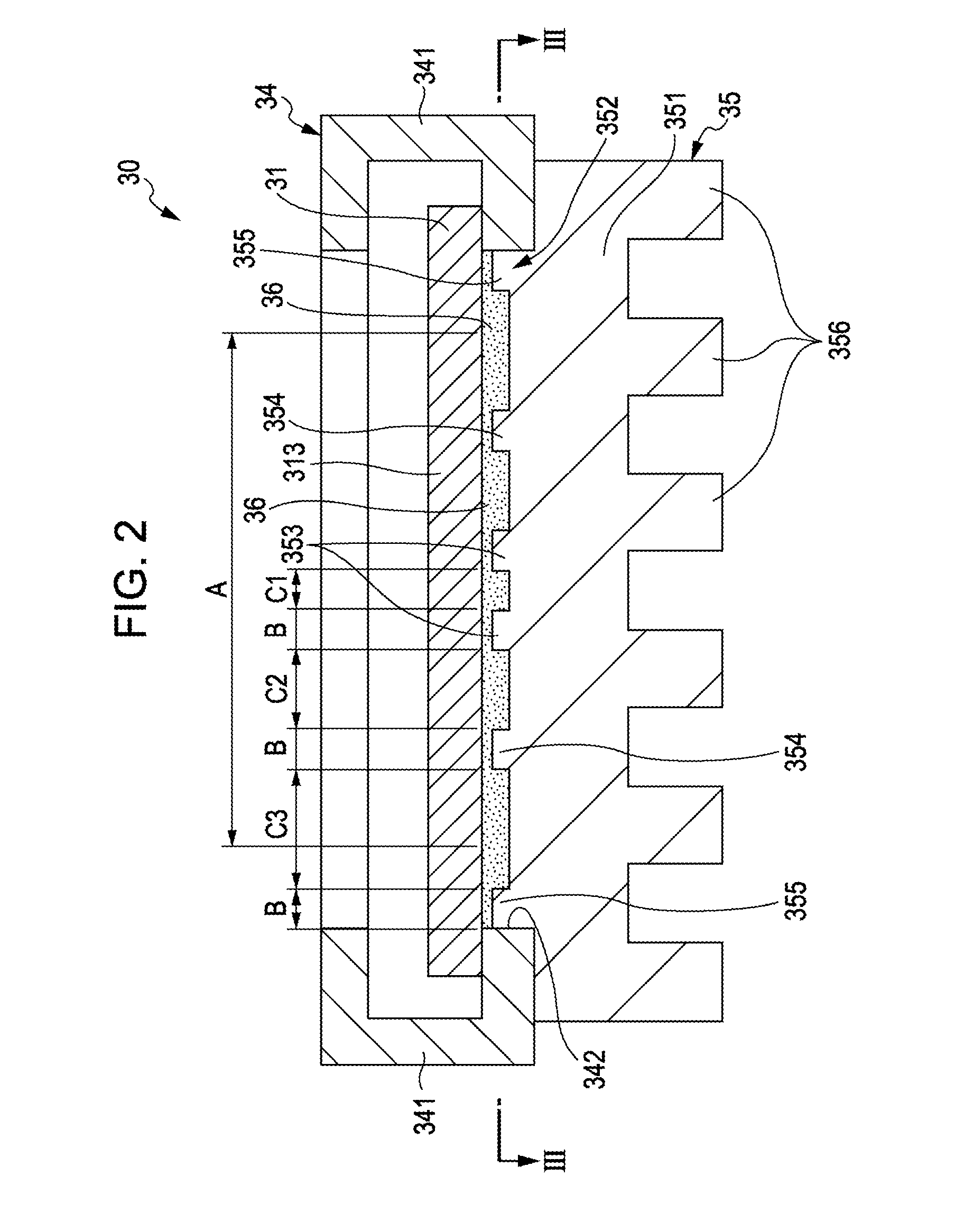
[0051]The first through third heat receiving convexes 353 through 355 have the same width and are provided concentrically about the heat reception acceleration center portion. Further, the inner diameter C1, the space C2, and the space C3 are set to be larger in this order. Therefore, tip surface area ratios of the first through third heat receiving convexes 353 through 355 are larger on the heat reception acceleration center portion rather than on the heat reception acceleration end portion. Therefore, a heat receiving efficiency on the center portion of which temperature is higher than that of the frame portion on the display region 313 can be made larger than that on the frame portion. Accordingly, temperature distribution on the display region 313 can be made uniform, thereby suppressing deterioration of the liquid crystal due to high temperature. This mak...
second embodiment
[0054]Next, a second embodiment of the invention is described.
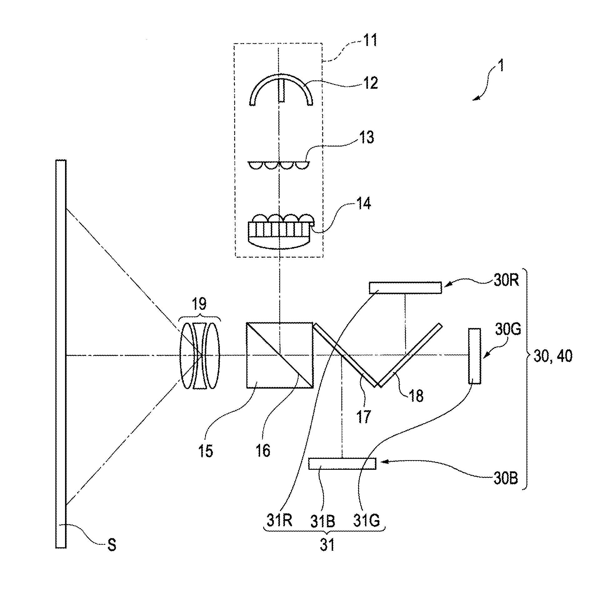
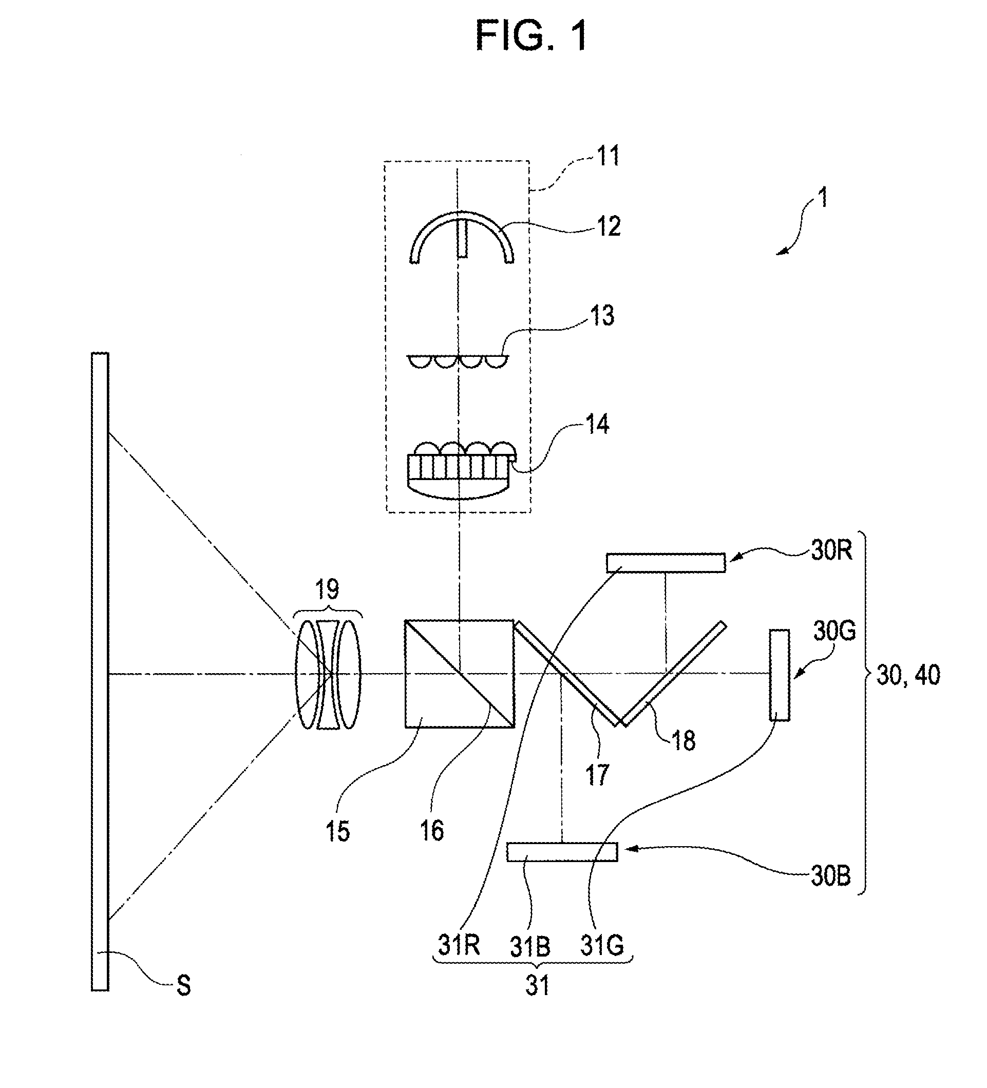
[0055]It is to be noted that a reflection type electrooptic device 40 according to the second embodiment is arranged in place of the reflection type electrooptic device 30 in the first embodiment as illustrated in FIG. 1.
[0056]FIG. 4 is a cross-sectional view illustrating a configuration of the reflection type electrooptic device 40. FIG. 5 is a cross-sectional view of FIG. 4 cut along a line V-V.
[0057]It is to be noted that since a basic configuration of the second embodiment is the same as that in the first embodiment, same reference numerals denote common parts and description thereof is not repeated.
[0058]As illustrated in FIG. 4 and FIG. 5, a heat dissipating member 45 of the reflection type electrooptic device 40 includes a heat receiving portion 351 having a fitting portion 352.
[0059]Further, first, second and third heat receiving convexes 453, 454, 455 formed concentrically are provided on the fitting portion 352....
first modification
[0063]FIG. 6 is a plan view illustrating a heat dissipating member 55 according to a modification of the first embodiment of the invention when seen from a normal line direction of the heat receiving portion 351. In the modification, first through third heat receiving convexes 553 through 555 as columnar projections are arranged in place of the first through third heat receiving convexes 353 through 355 having ring shapes in the first embodiment. The first through third heat receiving convexes 553 through 555 are arranged so as to be in a discrete manner when seen from the normal line direction of the heat receiving portion 351. Projections provided along a smallest circle correspond to the first heat receiving convexes 553. Projections provided along a second-smallest circle correspond to the second heat receiving convexes 554. Further, projections provided along a largest circle correspond to the third heat receiving convexes 555. The first through third heat receiving convexes 55...
PUM
 Abstract
Description
Claims
Application Information