Fusing device of electro-photographic image-forming apparatus and method of using

Inactive Publication Date: 2005-06-30
S PRINTING SOLUTION CO LTD
View PDF8 Cites 5 Cited by
  • Summary
  • Abstract
  • Description
  • Claims
  • Application Information

AI Technical Summary

Benefits of technology

[0015] The present invention provides a fusing device installed in an electro-photographic image forming apparatus, in which a continuous belt can be quickly heated to a settling temperature and attain a uniform temperature distribution and a method thereof.

Problems solved by technology

Use of a conventional fusing device, such as the fusing device 10 shown in FIG. 1, that adopts a halogen lamp as a heat source causes unnecessary power consumption.
For this reason, when the conventional fusing device is turned on to perform a print job, it takes a long time to warm up until its temperature reaches a fusing temperature.
Since a fusing roller of the conventional fusing device is heated by radiant heat generated by the heat source, a heat transfer speed is slow.
Also, since the heat of the heated fusing roller is delivered to paper when the paper contacts the fusing roller, it is impossible to timely compensate for a deviation in temperature caused by a reduction in the temperature, thus preventing adjustment of temperature dispersion.
Also, a nip caused when a pressurizing roller contacts the fusing roller has a narrow width, and thus, there is a limitation to forming an image at a high speed.
However, in this case, the volume of the fusing device is increased.
However, a high-thermal-capacity elastic layer of the continuous belt of the fusing device disclosed in published Japanese Patent Publication No. 2003-156961 is minimized, thus lowering the thermal storage capability of the fusing device.
For this reason, the fusing device is inconvenient to use since it needs to be frequently charged, thereby increasing power consumption and causing flicker.
Also, the fusing device using electromagnetic heating, disclosed in published Japanese Patent Publication No. 2002-182500, requires the continuous belt to include a magnetic layer, thereby increasing manufacturing costs.

Method used


Image

  • Fusing device of electro-photographic image-forming apparatus and method of using
  • Fusing device of electro-photographic image-forming apparatus and method of using
  • Fusing device of electro-photographic image-forming apparatus and method of using

Examples


Embodiment Construction

[0024] Hereinafter, exemplary embodiments of the present invention will be described in detail with reference to the accompanying drawings. Like reference numerals will represent like elements throughout the drawings.

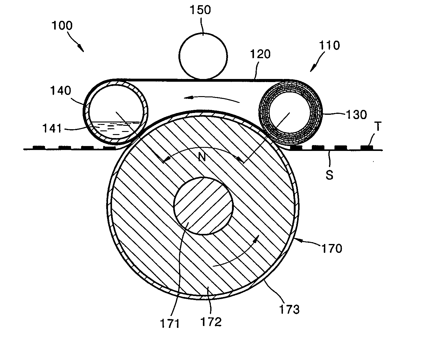
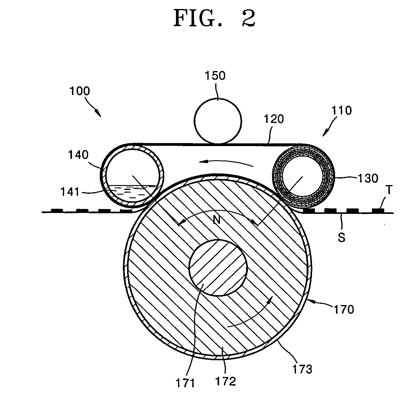
[0025] A fusing device 100 shown in FIG. 2, according to an embodiment of the present invention, includes a fusing belt 110 that includes a major heating roller 130, an auxiliary heating roller 140, and a continuous belt 120 that is rotated while being supported by the major and auxiliary heating rollers 130 and 140 and heated by the first major heating roller 130; and a pressurizing roller 170 that contacts the continuous belt 120, facing the fusing belt 110, and presses paper passing through a contact nip N between the continuous belt 120 and the pressurizing roller 170 toward the continuous belt 120.

[0026] The major heating roller 130 contacts an inner surface of the continuous belt 120. Also, as shown in FIG. 8, the major heating roller 130 includes an outer rolle...


PUM


Abstract

A fusing device installed in an electro-photographic image forming apparatus and method are provided. The fusing device includes a fusing belt having a continuous belt for rotating while being supported by at least two rollers, receiving heat from the at least two rollers, and delivering the heat to an image transferred onto paper; and a pressurizing roller for contacting the continuous belt and applying pressure onto the paper.

Description

[0001] This application claims the benefit under 35 U.S.C. 119(a) of Korean Patent Application No. 2003-101579 filed on Dec. 31, 2003 in the Korean Intellectual Property Office, the entire contents of which is incorporated herein by reference. BACKGROUND OF THE INVENTION [0002] 1. Field of the Invention [0003] The present invention relates to an electro-photographic image forming apparatus and method of using the same. More particularly, the present invention relates to a fusing device installed in an electro-photographic image forming apparatus that applies heat and pressure onto an image so that the image can be fused to the paper and a method of using the same. [0004] 2. Description of the Related Art [0005] In general, an electro-photographic image forming apparatus includes a fusing device that applies heat and pressure onto an image transferred onto paper so that the image can be fused onto the paper. [0006] A heating unit 12 with a halogen lamp is installed in a center portio...

Claims


Application Information

Patent Timeline
IPC IPC(8): G03G15/20
CPCG03G15/2064G03G2215/2016G03G15/2025G03G2215/2041G03G2215/2032G03G15/2053G03G2215/2029
Inventor CHO, DURK-HYUN
Owner S PRINTING SOLUTION CO LTD
Why Eureka
Try Eureka