
Shift device

一种换挡装置、挡孔的技术,应用在控制装置、传动装置控制、运输和包装等方向,能够解决无法有效地限制换挡杆转动、邻接部强度降低等问题,达到抑制小型化、抑制强度降低的效果

Inactive Publication Date: 2014-06-11
KK TOKAI RIKA DENKI SEISAKUSHO
View PDF7 Cites 0 Cited by
  • Summary
  • Abstract
  • Description
  • Claims
  • Application Information

AI Technical Summary

Problems solved by technology

In this case, if the abutment portion is downsized in the direction along the shift groove along with the miniaturization along the direction of the shift groove of the guide plate, the strength of the abutment portion is reduced, and the abutment portion may not be effective. limit the rotation of the shift lever

Method used


Image

  • Shift device
  • Shift device
  • Shift device

Examples


no. 1 approach

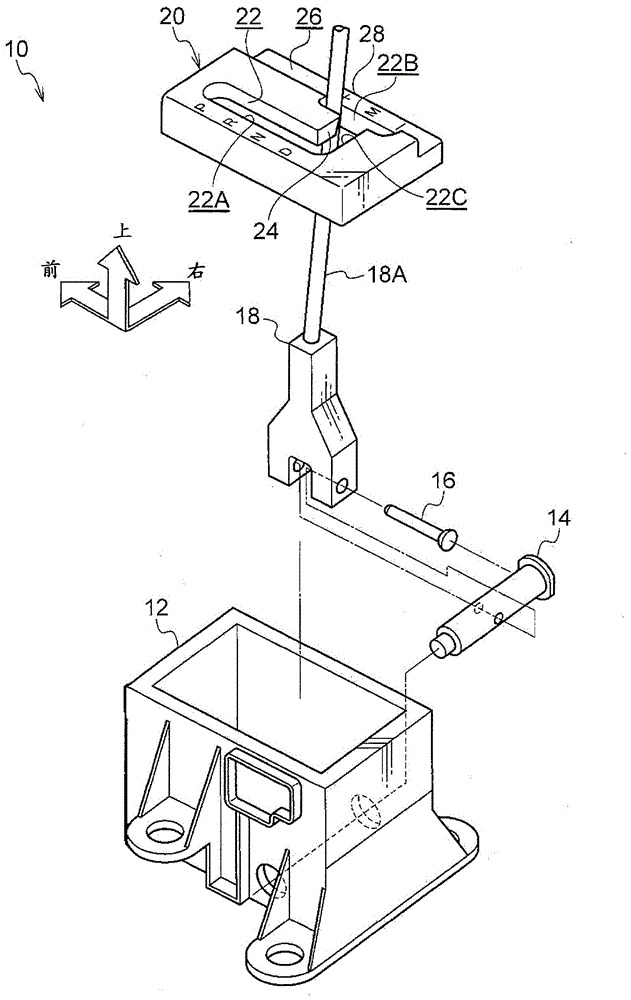
[0020] figure 1 In , the shift lever device 10 as the shift device according to the first embodiment of the present invention is shown in an exploded perspective view viewed obliquely from the left rear of the vehicle, figure 2 The selector lever device 10 is shown in a sectional view viewed from the rear of the vehicle. In addition, in the drawings, the front of the vehicle is indicated by an arrow FR, the right side of the vehicle is indicated by an arrow RH, and the upward direction is indicated by an arrow UP.

[0021] The shift lever device 10 of the present embodiment is a so-called floor-type shift lever, and is installed on a floor portion (floor) of the vehicle interior that is the vehicle body side.

[0022] Such as figure 1 as well as figure 2 As shown, the shift lever device 10 includes a substantially rectangular parallelepiped box-shaped case 12 as a supporting member. The case 12 is fixed to the floor portion of the vehicle interior and has an open upper su...


PUM


Abstract

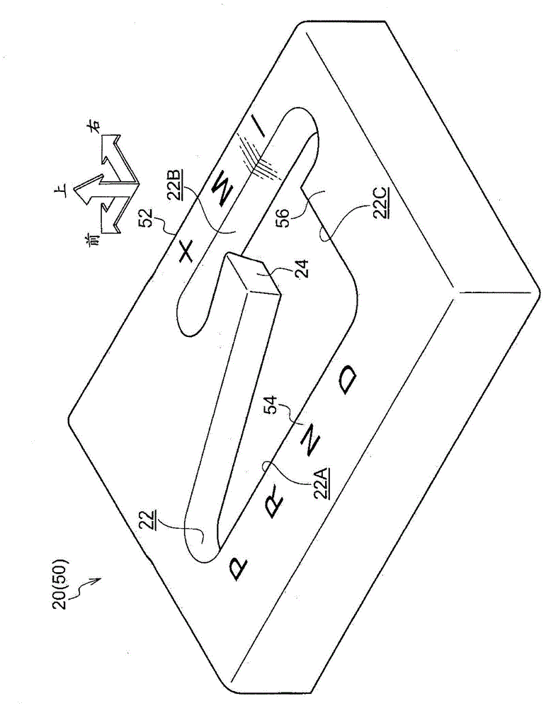
The present invention provides a shift device capable of suppressing a reduction in the strength of an adjacent portion even if a restriction member is reduced in size along the direction of a shift hole. In a strength gate (20) of a shift lever device (10), a shift hole (22) is provided with an automatic transmission hole (22A), a manual transmission hole (22B), and a communication hole. The strength gate is provided with a peninsular portion (24) that is adjacent to the automatic transmission hole (22A), the manual transmission hole (22B) and the communication hole, and an opposing portion (28) that is on the opposite side of the manual transmission hole (22B) to the peninsular portion (24). The peninsular portion (24) is disposed to a front side with respect to the opposing portion (28). A reduction in the size of the peninsular portion (24) along the vehicle left-right direction can accordingly be suppressed even if the strength gate (20) is reduced in size along the vehicle left-right direction, thereby enabling a reduction in the strength of the peninsular portion (24) to be suppressed.

Description

technical field [0001] The present invention relates to a shifting device for changing a shifting position by rotating a shifting member. Background technique [0002] In the shift lever device described in Patent Document 1 below, the shift lever is rotatably inserted into a shift groove of a guide plate, and an automatic transmission mode selection area and a manual transmission mode selection area are provided in the shift groove. Moreover, in the shift groove, the selection area of ​​the automatic transmission mode and the selection area of ​​the manual transmission mode are communicated through the communication area, and the selection area of ​​the automatic transmission mode, the selection area of ​​the manual transmission mode, and the selection area adjacent to the communication area are provided on the guide plate. adjacency of . [0003] However, in this shift lever device, it is often necessary to downsize (reduce) the guide plate in the direction along the shif...

Claims


Application Information

Patent Timeline
Patent Type & Authority Applications(China)
IPC IPC(8): B60K20/02
CPCF16H59/10F16H59/0204F16H2059/0239Y10T74/20159
Inventor 加藤政史加古健一森勇人中西谦二樋口怜士岩崎佳史后藤健太
Owner KK TOKAI RIKA DENKI SEISAKUSHO
Learn More