
Rotors, electric motors, compressors and refrigeration and air conditioners

A rotor and gap technology, applied in the field of refrigeration and air conditioners, can solve the problems of magnetic force reduction, motor efficiency deterioration, torque reduction, etc., and achieve the effect of suppressing torque ripple and torque reduction

Active Publication Date: 2019-06-21
MITSUBISHI ELECTRIC CORP
View PDF7 Cites 0 Cited by
  • Summary
  • Abstract
  • Description
  • Claims
  • Application Information

AI Technical Summary

Problems solved by technology

[0006] However, there is a problem that the magnetic force decreases due to the arrangement of the slit, the torque decreases, and the motor efficiency deteriorates

Method used


Image

  • Rotors, electric motors, compressors and refrigeration and air conditioners
  • Rotors, electric motors, compressors and refrigeration and air conditioners
  • Rotors, electric motors, compressors and refrigeration and air conditioners

Examples


Embodiment approach 1

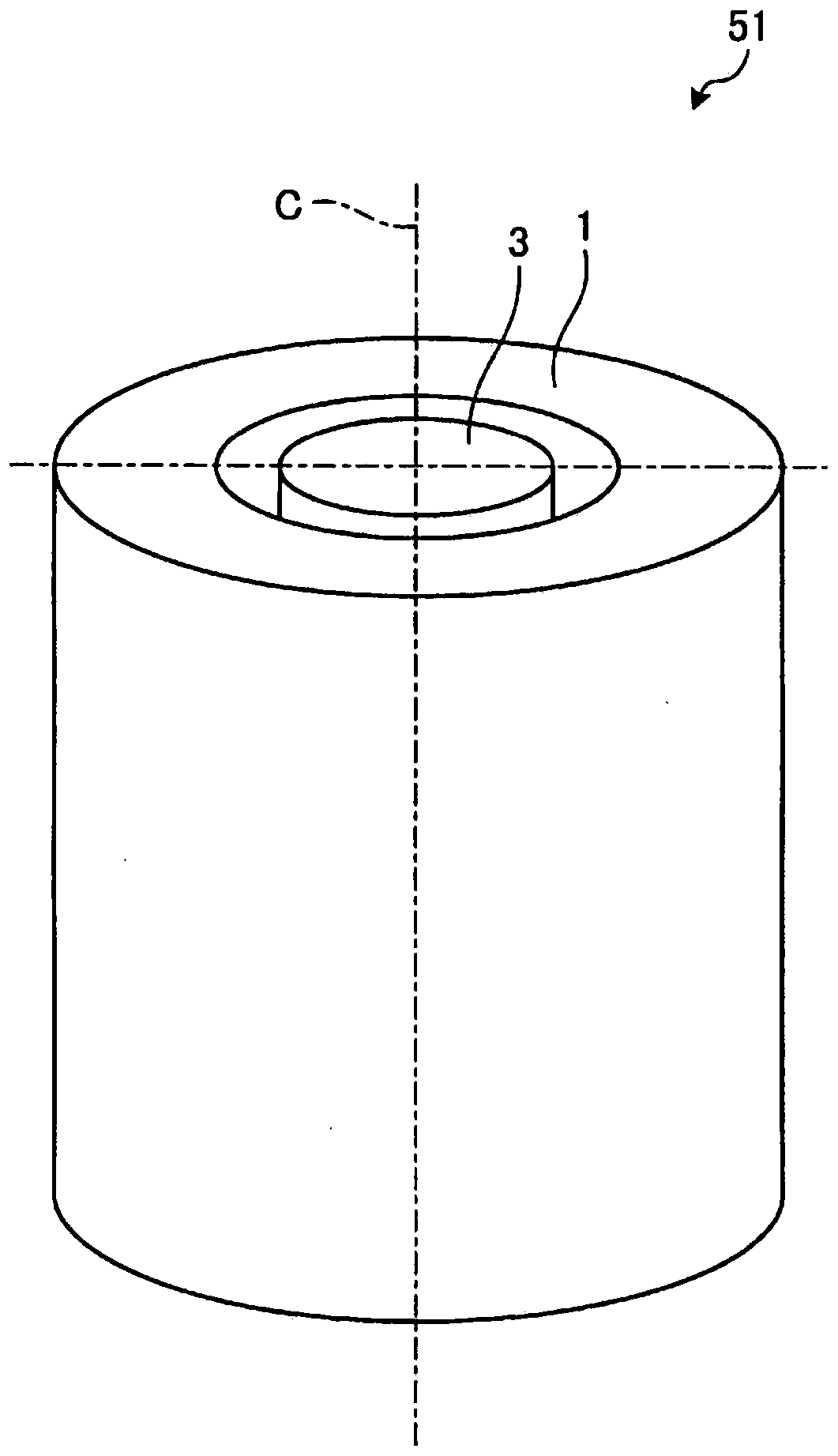
[0025] figure 1 It is a perspective view showing a schematic configuration of the motor according to Embodiment 1 of the present invention. The motor 51 includes a cylindrical stator 1 and a rotor 3 provided inside the stator 1 and rotating around a central axis C of the stator 1 .

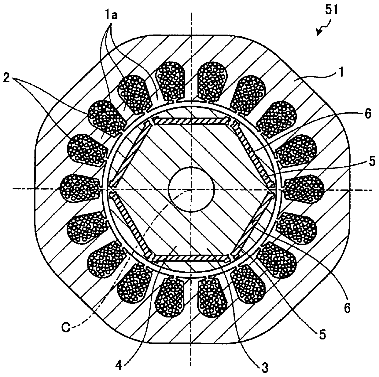
[0026] figure 2 It is a cross-sectional view of the motor 51 according to Embodiment 1 taken along a plane perpendicular to the central axis C. FIG. The stator 1 is configured by winding a winding 2 around a plurality of teeth 1 a protruding inward. The rotor 3 exhibits a cylindrical or cylindrical shape extending along the central axis C. As shown in FIG. The rotor 3 is arranged with a gap between it and the stator 1 .

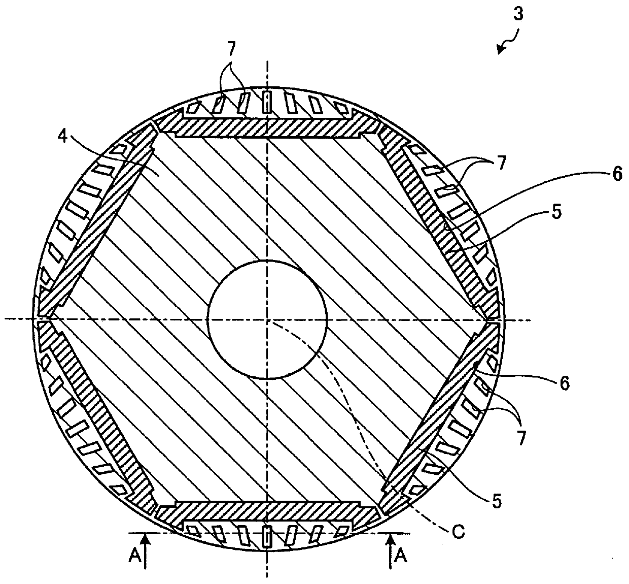
[0027] image 3 It is a cross-sectional view of the rotor 3 in Embodiment 1 taken along a plane perpendicular to the central axis C. The rotor 3 includes an iron core 4 formed by laminating a plurality of electromagnetic steel sheets in a direction along the central axis C...


PUM


Abstract

The rotor (3) includes: an iron core (4) in a cylindrical or cylindrical shape; and a plurality of magnets arranged at equal intervals in the circumferential direction with respect to the central axis (C) of the iron core (4) and embedded in the iron core (4), the iron core (4) has a first end face (41), a second end face (42) and a central part (43) arranged between the first end face (41) and the second end face (42). ), in each of the first end surface (41), the second end surface (42) and the central portion (43), at a position farther from the central axis (C) of the iron core (4) than the plurality of magnets, At least one void (7) is formed, and the third cross-sectional area of ​​the central portion (43) is larger than the first cross-sectional area of ​​the first end face (41) and the second cross-sectional area of ​​the second end face (42).

Description

technical field [0001] The present invention relates to a rotor, a motor, a compressor and a refrigerating and air-conditioning machine in which a permanent magnet is inserted into an iron core. Background technique [0002] In recent years, there is a tendency to demand improvement in the efficiency of electric motors due to increased awareness of energy saving. Therefore, there has been proposed a motor in which efficiency is improved by using a rotor in which a permanent magnet is inserted into an iron core. [0003] In such a motor, the torque ripple during operation and the radial excitation force may increase due to the influence of the iron core portion on the outer peripheral side than the inserted permanent magnet. Torque ripple is a ripple generated due to a state change of torque during operation. Since the torque ripple causes vibration and noise, it is necessary to reduce the torque ripple together with the improvement of efficiency. In Patent Document 1, tor...

Claims


Application Information

Patent Timeline
Patent Type & Authority Patents(China)
IPC IPC(8): H02K1/27
CPCH02K7/14H02K2213/03H02K29/03F04B35/04H02K1/276H02K1/02H02K2207/03
Inventor 石川淳史
Owner MITSUBISHI ELECTRIC CORP
Learn More