Motor
a motor and motor technology, applied in the field of motors, can solve the problems of reducing power density, limiting the motor, increasing the weight of the rotor, etc., and achieve the effects of improving durability, reducing torque, and improving power density
- Summary
- Abstract
- Description
- Claims
- Application Information
AI Technical Summary
Benefits of technology
Problems solved by technology
Method used
Image
Examples
first embodiment
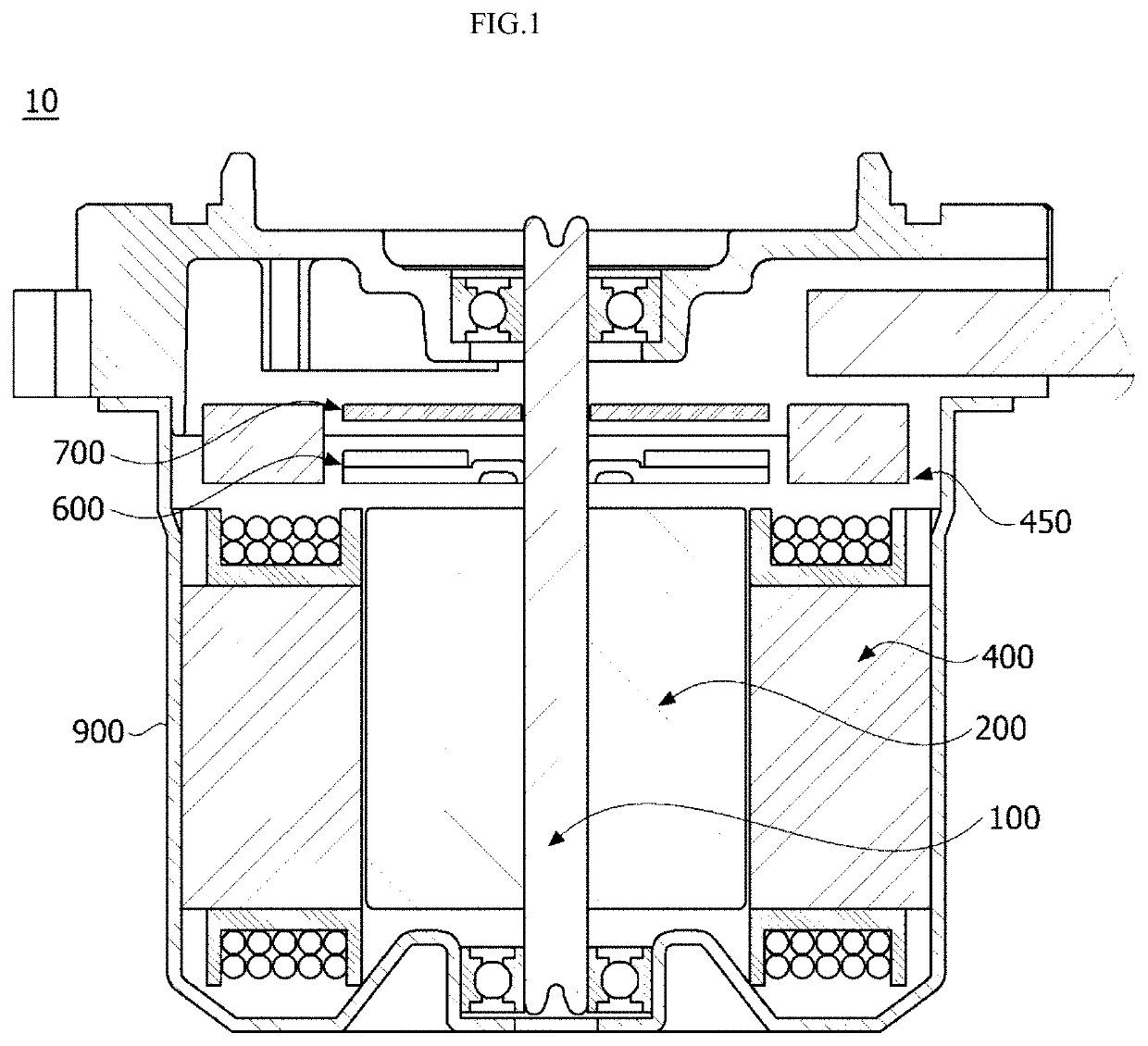
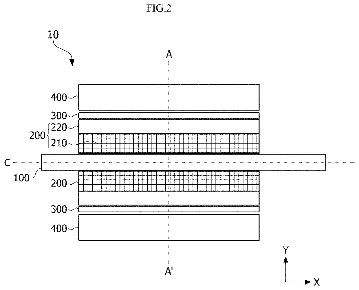
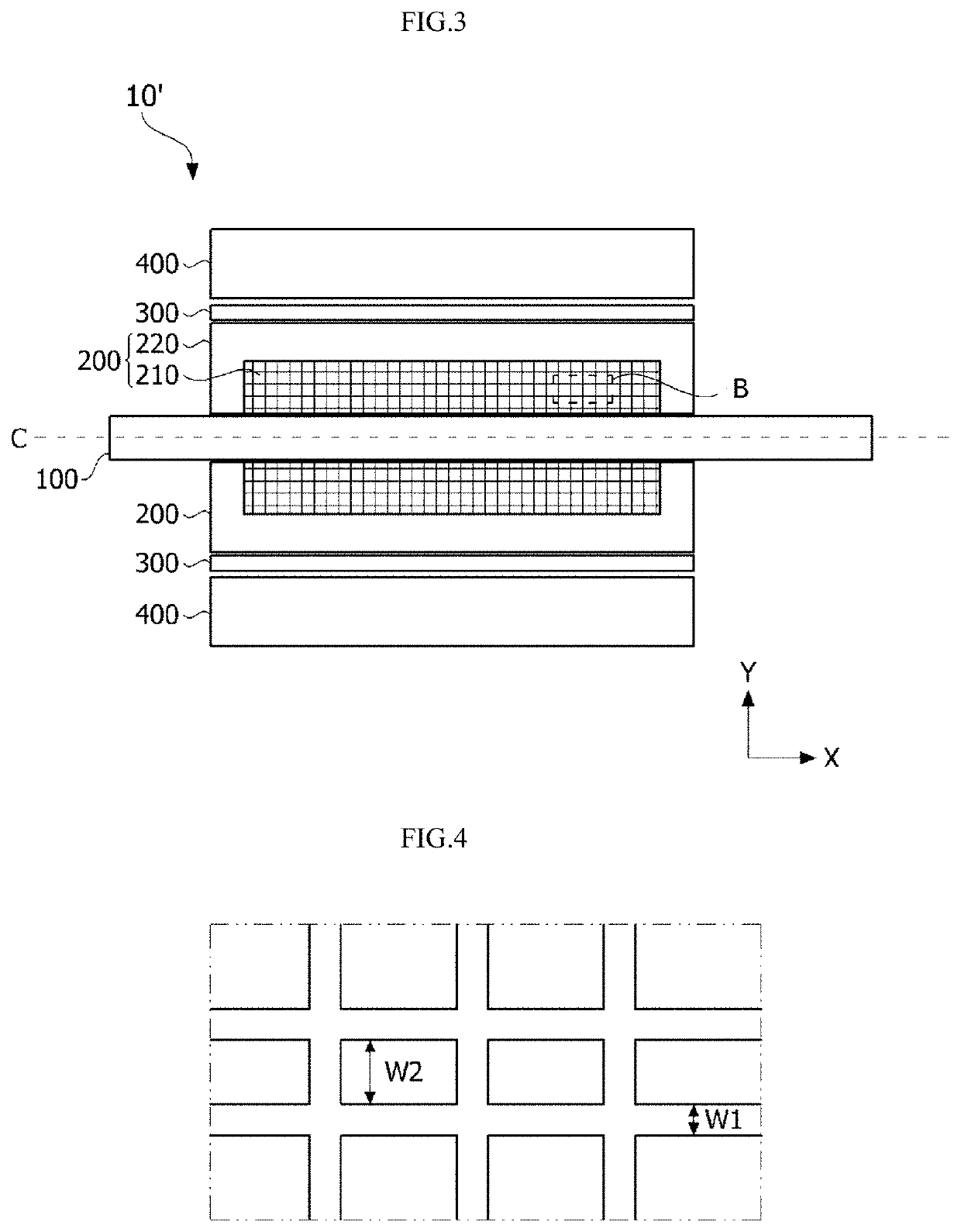
[0063]Referring to FIGS. 1 and 2, a motor 10 includes a rotary shaft 100, a rotor 200, a magnet 300, and a stator 400. First, the rotary shaft 100 may be disposed at a center of the motor 10. For example, the rotary shaft 100 may be disposed on a central axis C of the motor 10. Further, the rotary shaft 100 may be coupled to the rotor 200. More specifically, when an electromagnetic interaction between the rotor 200 and the stator 400 occurs due to supply of currents, the rotor 200 rotates, and thus the rotary shaft 100 may rotate. In this case, the rotary shaft 100 may rotate with respect to the central axis C to transfer power to an external device. Further, the rotary shaft 100 may have a cylindrical shape, and the central axis C may be a straight line which connects centers of circles in the rotary shaft 100.
[0064]The rotary shaft 100 may be surrounded by the rotor 200, the magnet 300, and the stator 400 which will be described later. The rotor 200, the magnet 300, and the stato...
second embodiment
[0102]FIG. 10 is a side cross-sectional view of a motor FIG. 11 is a cross-sectional view taken along line B-B′ of the motor in FIG. 10, FIG. 12 is an enlarged view of a seventh region in FIG. 11, and FIG. 13 is an enlarged view of an eighth region in FIG. 12.
[0103]Hereinafter, the motor according to the second embodiment of the present invention will be described with reference to FIGS. 10 to 13. However, a motor 20 according to the second embodiment of the present invention is the same as the motor shown in FIG. 2 and overlapping configurations will be described using the same reference numerals.
[0104]Referring to FIGS. 10 to 13, the motor 20 according to the second embodiment of the present invention includes a rotary shaft 100, a rotor 500, a magnet 300, and a stator 400.
[0105]The rotor 500 and the stator 400 may electrically interact. When the electrical interaction is caused, the rotor 500 may rotate. The rotary shaft 100 may also rotate in conjunction with rotation of the ro...
third embodiment
[0115]FIG. 14 is a side cross-sectional view of a motor according to the present invention.
[0116]Further, as shown in FIG. 14, a non-pattern rotor core portion 530 in which a pattern is not formed may be disposed between a patterned portion 510 and a rotary shaft 100.
[0117]Meanwhile, a jig hole (not shown) on which a jig for assembly is seated may be formed in the patterned portion 510.
[0118]The outer contour portion 520 forms the outermost contour of a rotor 500 and includes an outer circumferential surface 521 and an inner circumferential surface 522.
[0119]The outer circumferential surface 521 faces a stator 400, and the inner circumferential surface 522 faces a central axis C.
[0120]Further, a plurality of magnets 300 are disposed on the outer circumferential surface 521, and a plurality of protrusion portions 522a and 522b protrude toward the central axis C from the inner circumferential surface 522.
[0121]Meanwhile, guide protrusions (not shown) which guide disposition of the plu...
PUM
 Abstract
Description
Claims
Application Information
 - R&D
- Intellectual Property
- Life Sciences
- Materials
- Tech Scout
- Unparalleled Data Quality
- Higher Quality Content
- 60% Fewer Hallucinations
Browse by: Latest US Patents, China's latest patents, Technical Efficacy Thesaurus, Application Domain, Technology Topic, Popular Technical Reports.
© 2025 PatSnap. All rights reserved.Legal|Privacy policy|Modern Slavery Act Transparency Statement|Sitemap|About US| Contact US: help@patsnap.com


