Three-roller transmission veneer reeling machine

A plate rolling machine and auxiliary transmission technology, which is applied in the field of plate rolling machines, can solve the problems that the third pressure roller cannot be driven, and achieve the effects of saving labor costs, ensuring quality, and reducing wear and indentation

Inactive Publication Date: 2014-06-11
LIYANG CITY ZHENGXIANG PRECISION MACHINERY
View PDF5 Cites 5 Cited by
  • Summary
  • Abstract
  • Description
  • Claims
  • Application Information

AI Technical Summary

Problems solved by technology

[0002] The existing plate bending machine includes a first pressure roller, a second pressure roller, and a third pressure roller. The third pressure roller (upper pressure roller) is located on the upper part between the first pressure roller and the second pressure roller. The first pressure roller and the second pressure roller The second pressure rollers are all connected with the main transmission mechanism that drives the first and second pressure rollers to rotate; the third pressure roller cannot be driven

Method used


Image

  • Three-roller transmission veneer reeling machine
  • Three-roller transmission veneer reeling machine

Examples


Embodiment Construction

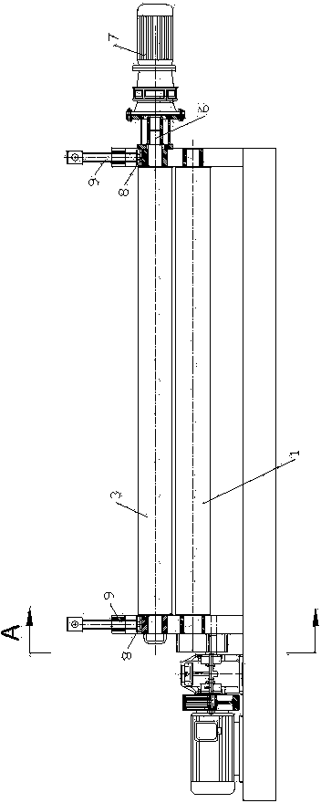
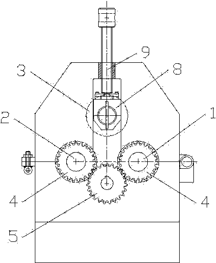
[0009] see figure 1 , 2 The three-roller transmission plate bending machine shown includes three parallel first rollers 1, second rollers 2, and third rollers 3 that are rotatably arranged on the frame. The third roller 3 is positioned on the first roller The upper part between the second pressure roller.

[0010] The gears 4 at one end of the first pressure roller and the second pressure roller are all meshed with the gear 5 on the output shaft of the belt main transmission mechanism. The third pressing roller 3 is connected with the motor 7 through the coupling sleeve 6 , the two ends of the third pressing roller 3 are rotatably arranged on the slider 8 , and the motor 7 is fixed on the slider 8 . The slide block 8 is arranged on the frame to slide up and down through the lead screw nut structure 9 .

[0011] This equipment uses a geared motor to drive the upper pressure roller to rotate. Realize the simultaneous rotation of the upper and lower pressure rollers. When t...


PUM


Abstract

The invention provides a three-roller transmission veneer reeling machine. The three-roller transmission veneer reeling machine can facilitate reeling and comprises a first press roller, a second roller and a three roller which are rotatably arranged in parallel on a machine frame, wherein the third press roller is arranged above and between the first press roller and the second press roller, the first press roller and the second press roller are connected with a main transmission mechanism which drives the first press roller and the second press roller to rotate, and the third press roller is connected with an auxiliary transmission mechanism which drives the three press roller to rotate.

Description

technical field [0001] The technology relates to a plate rolling machine. Background technique [0002] The existing plate bending machine includes a first pressure roller, a second pressure roller, and a third pressure roller. The third pressure roller (upper pressure roller) is located on the upper part between the first pressure roller and the second pressure roller. The first pressure roller and the second pressure roller The second pressure rollers are all connected with the main transmission mechanism that drives the first pressure roller and the second pressure roller to rotate; the third pressure roller cannot be driven. When the plate to be processed is round or conical, because the upper pressing roller does not drive, it is difficult to roll the plate to be processed, or it cannot be rolled at all. Contents of the invention [0003] The purpose of this technology is to provide a three-roller drive plate rolling machine which is more convenient for rolling. [...

Claims


Application Information

Patent Timeline
Patent Type & Authority Applications(China)
IPC IPC(8): B21D5/14
Inventor 李锁峰
Owner LIYANG CITY ZHENGXIANG PRECISION MACHINERY
Why Eureka
Try Eureka