Anti-loosening mechanism for quick release component

An anti-dropping and wrench technology, applied in the connection of connecting components, mechanical equipment, rods, etc., can solve the problems of quick release group failure, wrench collision, wrench loosening, etc.

Inactive Publication Date: 2014-06-11
GIANT KUNSHAN
View PDF9 Cites 7 Cited by
  • Summary
  • Abstract
  • Description
  • Claims
  • Application Information

AI Technical Summary

Problems solved by technology

However, in the actual process, the wrench is often collided, causing the wrench to loosen and the quick release assembly to fail

Method used


Image

  • Anti-loosening mechanism for quick release component
  • Anti-loosening mechanism for quick release component
  • Anti-loosening mechanism for quick release component

Examples


Embodiment Construction

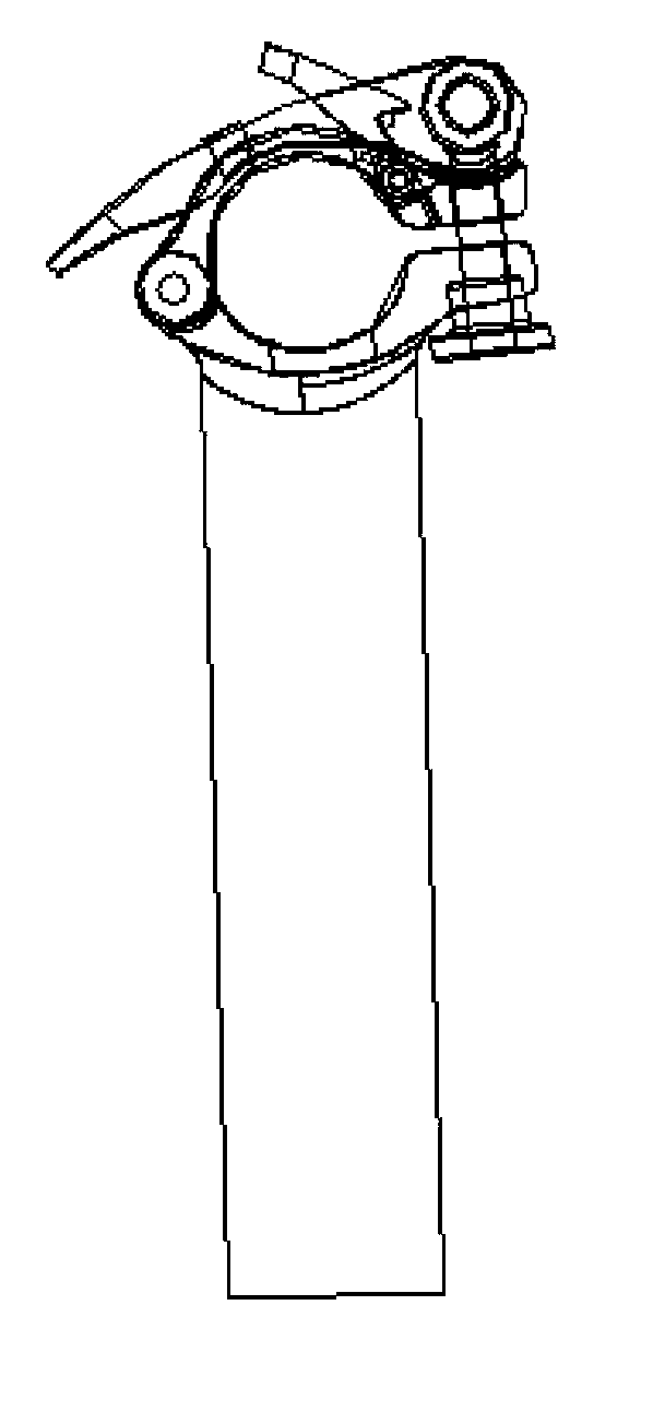
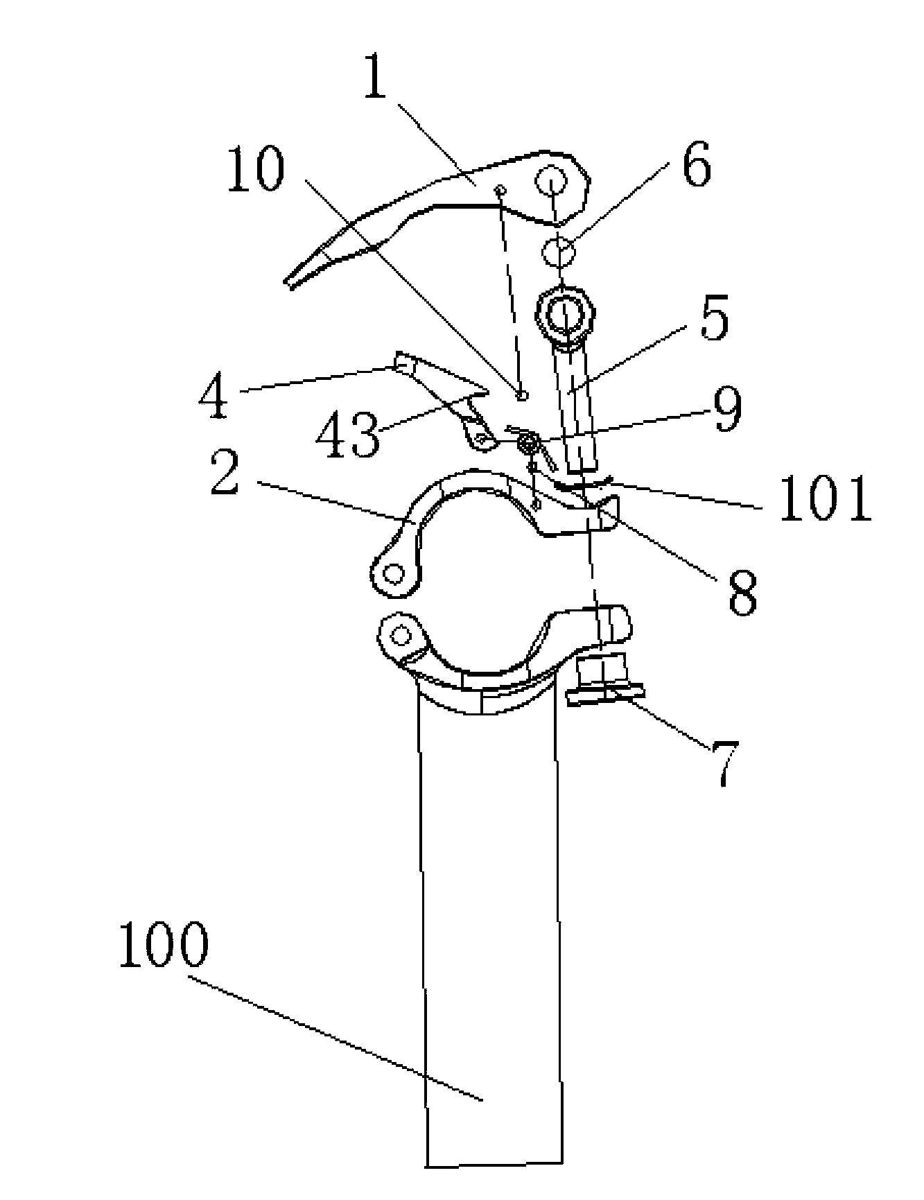
[0017] to combine figure 1 , figure 2 with image 3 , as described in detail below:

[0018] An anti-off mechanism for a quick-release group, installed between the upper wrench 1 and the upper cover 2 of the quick-release group, the quick-release group includes a lower cover 3 that is fixed to one side of the upper cover 2 and moves through the upper cover 2 After the upper cover plate 2 and the other side of the lower cover plate 3, screw a bolt 5 with a nut 7 and a rotating shaft 6 that passes through the root of the bolt 5. The ends of the wrench form a pair of supporting feet 11 with U-shaped openings. 12. The ends of the pair of supporting feet 11 and 12 are respectively sleeved on the two ends of the rotating shaft 6, and the ends of the pair of supporting feet 11 and 12 respectively have eccentric edges. Wrench 4, the anti-off wrench 4 forms a pair of anti-off supporting feet 41, 42 side by side. A clamping shaft 10 is fixed between the supporting legs 11 and 12, a...


PUM


Abstract

The invention discloses an anti-loosening mechanism for a quick release component. The anti-loosening mechanism is mounted between an upper wrench and an upper cover plate of the quick release component; the quick release component comprises a lower cover plate, a bolt and a rotary shaft, wherein the lower cover plate is fixedly connected with one side of the upper cover plate in a rotating manner; the bolt movably penetrates through the other sides of the upper and lower cover plates to be screwed by a nut; the rotary shaft movably passes through the root part of the bolt; a pair of support legs in U-shape are formed at the end parts of the wrench; the end parts of the pair of support legs are sleeved on the two ends of the rotary shaft; the end parts of the support legs are provided with eccentric edges respectively; the anti-loosening mechanism comprises an anti-loosening wrench positioned in the U-shaped opening; the anti-loosening wrench forms a pair of anti-loosening support legs side by side; the end parts of the pair of anti-loosening support legs are rotationally fixed on the upper cover plate through an anti-loosening fixed rotary shaft; a clamping shaft is fixedly arranged between the support legs in a penetrating manner; the anti-loosening wrench is provided with a clamping slot for the clamping shaft to be buckled, corresponding to the clamping shaft. The anti-loosening mechanism for the quick release component can effectively prevent the quick release component from loosening when the wrench is clamped, and also can facilitate the opening of the quick release component.

Description

technical field [0001] The invention belongs to the improvement of a quick release group on pipe fitting clamping or pipe fitting folding, and particularly relates to an improvement capable of preventing the wrench on the quick release group from loosening. Background technique [0002] At present, the clamping of pipe fittings or the folding and fixing of pipe fittings are all locked by the quick release group. The so-called quick release group is to use a bolt to move through the side of the upper cover plate and the lower cover plate used to clamp the pipe fittings or fold the pipe fittings, and then screw one. Nut, the upper cover and the other side of the lower cover are hinged, the root end of the bolt moves through a rotating shaft, and the two ends of the rotating shaft are respectively sleeved and fixed on a pair of legs on a wrench. The wrench is integrally formed as a The pair of supporting feet with a U-shaped opening, and the pair of supporting feet have eccentr...

Claims


Application Information

Patent Timeline
Patent Type & Authority Applications(China)
IPC IPC(8): F16B7/22
Inventor 周晓春唐志勇
Owner GIANT KUNSHAN
Why Eureka
Try Eureka