Method of forming distributed energy storage system by small hydropower cluster

A distributed energy storage and small hydropower station technology, applied in hydropower generation, mechanical equipment, energy saving and emission reduction, etc., can solve the problems of small capacity and inability to adapt to large-scale deployment of the power grid, and achieve stable operation, significant economic advantages and application value , the effect of high flexibility

Active Publication Date: 2016-11-09
HUAZHONG UNIV OF SCI & TECH
View PDF4 Cites 21 Cited by
  • Summary
  • Abstract
  • Description
  • Claims
  • Application Information

AI Technical Summary

Problems solved by technology

However, the pumped storage power generation device is only used for joint energy storage of a single hydropower station and other energy storage devices, and its capacity is small, which cannot meet the needs of large-scale deployment of the power grid

Method used


Image

  • Method of forming distributed energy storage system by small hydropower cluster
  • Method of forming distributed energy storage system by small hydropower cluster
  • Method of forming distributed energy storage system by small hydropower cluster

Examples


Embodiment 1

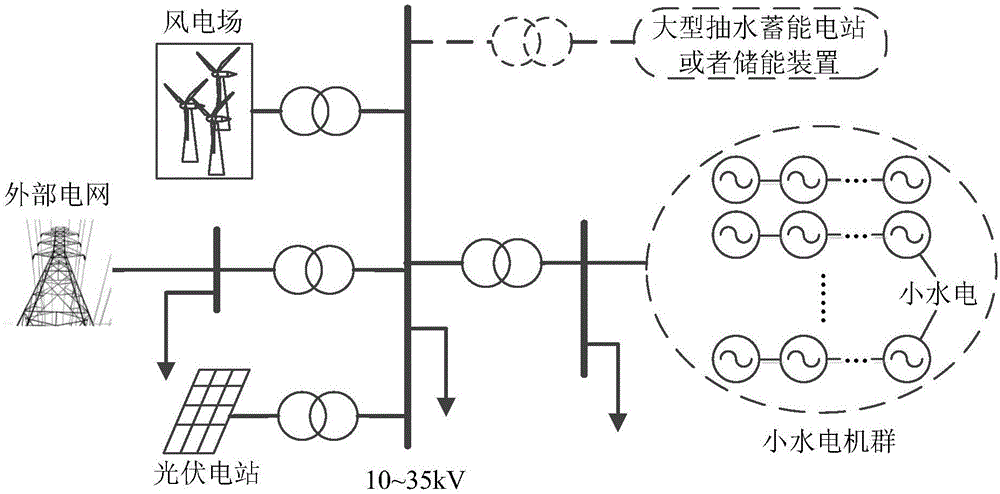
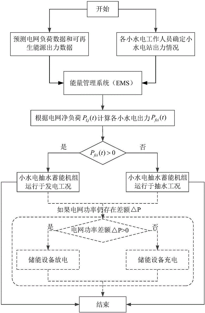
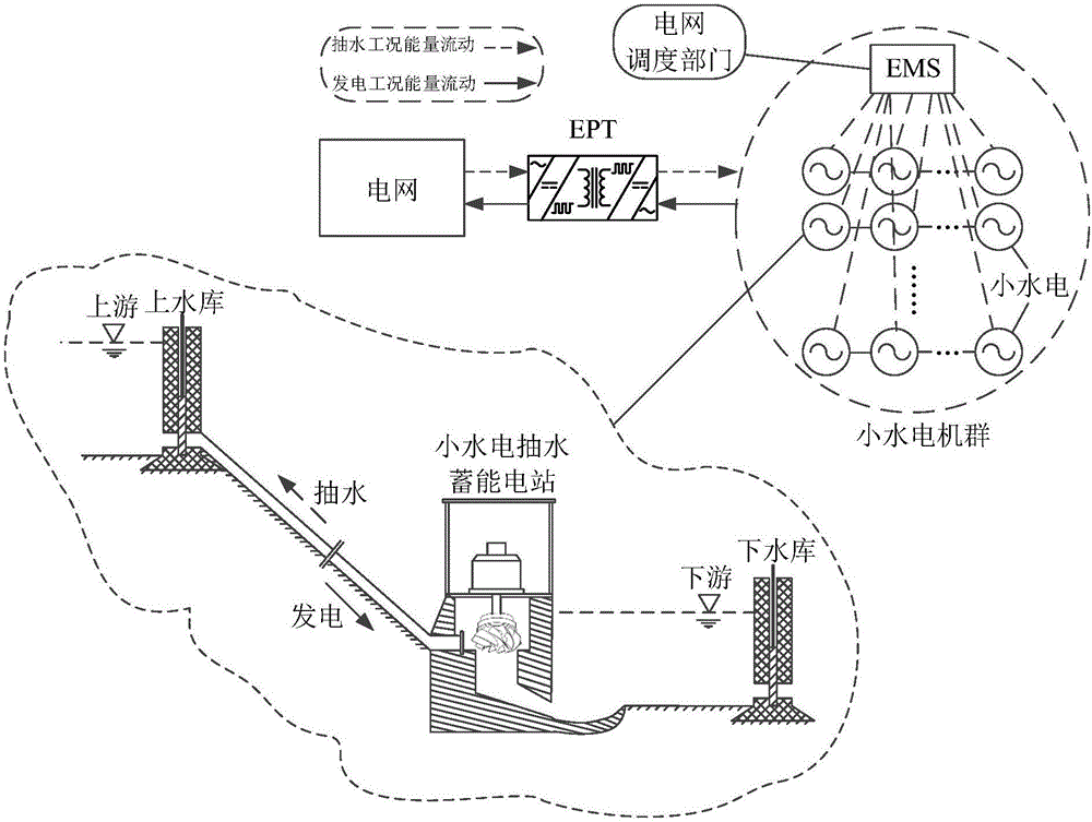
[0065] This embodiment is a coordinated and optimized embodiment involving small hydroelectric generators, wind power generation, and photovoltaic power generation. figure 1 In order to use the method of embodiment 1 to coordinate and optimize the grid structure; the small hydroelectric generator group is connected to the first input end of the 10-35kV substation, the wind farm is connected to the second input end of the 10-35kV substation, and the photovoltaic power station is connected to the 10-35kV substation. The third input terminal of a 35kV substation, the energy storage device is connected to the fourth input terminal of a 10-35kV substation, and the 10-35kV substation is connected to an external power grid through a transformer; figure 2 The flow chart for the coordination and optimization of grids containing small hydroelectric power plants and other renewable energy sources includes the following steps:

[0066] S1. Obtain the total net load value P of all small hydro...

Embodiment 2

[0083] Repeat Example 1 with the same steps described above, the difference is that the optimization target is the maximum total power generation of the small hydroelectric generator group, and the objective function is

Embodiment 3

[0085] Repeat Example 1 with the same steps as described, the difference is that the optimization goal is the minimum amount of discarded water of the small hydropower plant group, and the objective function is Among them, | represents the assumption. △V i (t) represents the amount of water discarded during the period t of the i-th small hydropower station.


PUM


Abstract

The invention discloses a method of forming a distributed energy storage system by a small hydropower cluster. The method comprises steps: a total net load value PLj(t) of all small hydropower stations at a tth time in an energy storage cycle T is acquired; according to an optimization objective, the total net load value PLj(t) and planned load pi(t) of an ith small hydropower station, the actual load pfci(t) of the ith small hydropower station is acquired; and according to the actual load pfci(t) of the ith small hydropower station, optimal efficiency control is carried out on a water pumping and water storing device of the ith small hydropower station, and the ith small hydropower station is made to operate under the optimal efficiency according to the actual load pfci(t), wherein the water pumping and water storing device is a hydraulic turbine, a water pump or a reversible hydraulic turbine. Through carrying out improvement on the small hydropower stations and using an energy management unit to manage the small hydropower stations in a unified mode, the multiple small hydropower stations can form a large energy storage system capable of power generation and energy storage, the problems of the operation efficiency and the utilization of the small hydropower stations can be solved, and the regulation capability of the power grid is improved.

Description

Technical field [0001] The invention belongs to the field of new energy power generation and electrical technology, and more specifically, relates to a method for forming a distributed energy storage system by a group of small hydroelectric machines. Background technique [0002] With the development of smart grids, the penetration rate of renewable energy in the grid has increased year by year, and the uncertainty of large-scale renewable energy output poses new challenges to the safe and economic operation of the grid. Therefore, the power grid must be equipped with a certain capacity of energy storage equipment to ensure the safe and stable operation of the power grid and peak-to-valley scheduling, while improving the absorption capacity of renewable energy. Mature large-capacity electric energy storage facilities at home and abroad include large-scale pumped storage power stations, compressed air energy storage and chemical energy storage. Among them, although large-scale pu...

Claims


Application Information

Patent Timeline
Patent Type & Authority Applications(China)
IPC IPC(8): H02J3/28H02J3/38F03B13/06
CPCF03B13/06H02J3/28H02J3/382H02J2203/20Y02E10/20Y02E60/16Y02E70/30Y02P90/50
Inventor 王丹毛承雄张高言田杰陆继明
Owner HUAZHONG UNIV OF SCI & TECH
Why Eureka
Try Eureka