
Clutch Controller

一种离合器控制、离合器的技术,应用在离合器、机械驱动离合器、相互啮合的离合器等方向,能够解决离合器旋转速度一致困难等问题

Active Publication Date: 2014-06-11
SUBARU CORP
View PDF6 Cites 5 Cited by
  • Summary
  • Abstract
  • Description
  • Claims
  • Application Information

AI Technical Summary

Problems solved by technology

[0005] However, even in the case of using a motor to synchronize the rotation speed, it is extremely difficult to completely match the rotation speed before and after the clutch. One rotation speed exceeds the other rotation speed state, and one rotation speed is lower than the other rotation speed. The state of velocity is repeated alternately

Method used


Image

  • Clutch Controller
  • Clutch Controller
  • Clutch Controller

Examples


Embodiment Construction

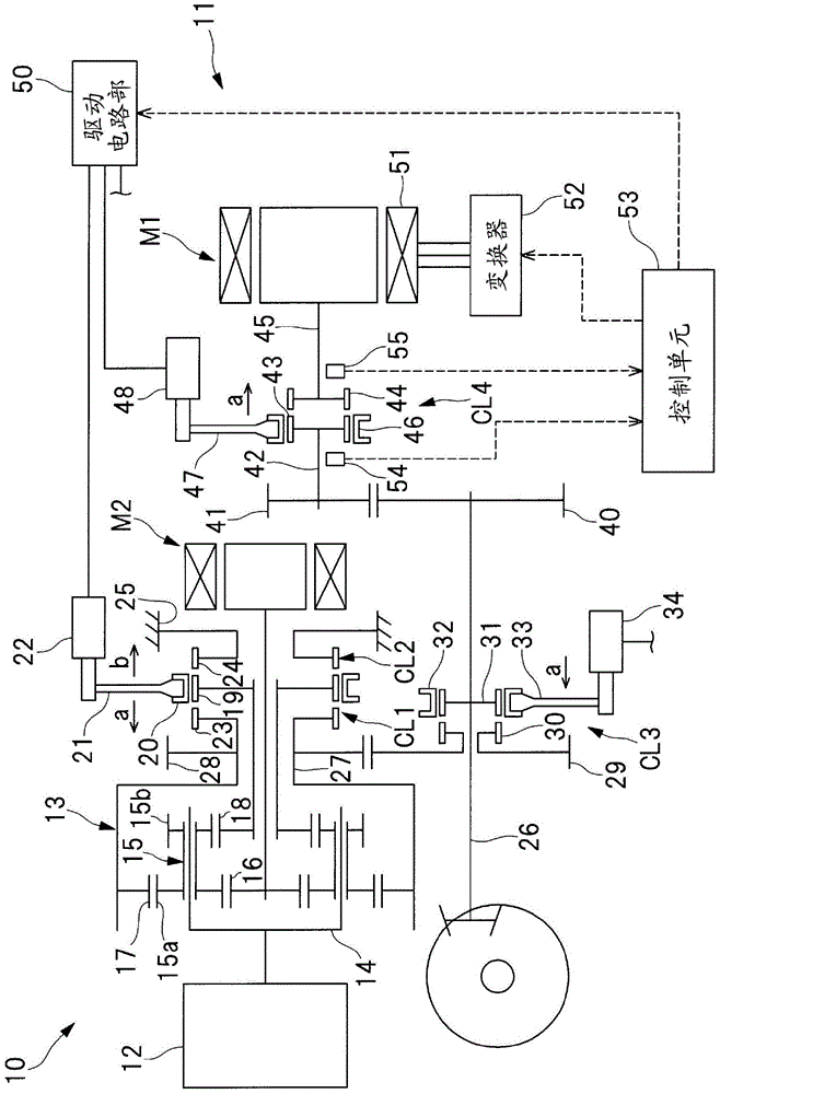
[0036] Hereinafter, embodiments of the present invention will be described in detail based on the drawings. figure 1 It is a schematic diagram showing a part of the powertrain 10 mounted on the hybrid vehicle and its control system. In this power train 10, a clutch control device 11 as an embodiment of the present invention is incorporated. Such as figure 1 As shown, in the power train 10, an engine 12, a first motor generator M1, and a second motor generator M2 are provided as power sources. In addition, in the power train 10, a clutch CL1, a clutch CL2, a clutch CL3, and a clutch CL4 are provided as meshing clutches. The clutches CL1 to CL4 are dog clutches, that is, meshing clutches that do not have a rotation synchronization mechanism such as a synchronizer ring.

[0037] Between the engine 12 and the motor generator M2, there is provided a power splitting mechanism 13 that splits the engine power to the driving wheels and the motor generator M2. The power split mechanism 1...


PUM


Abstract

The invention relates to a clutch controller which is capable of smoothly switching a claw clutch to the engaged state. The clutch controller is provided with a claw clutch which includes a clutch sleeve having an engagement tooth and a clutch wheel disposed coaxially with the clutch sleeve and having the engagement tooth and is switched between an engaged state where the engagement teeth are engaged with each other and a disengaged state where the engagement between the engagement teeth is released. An actuator moves either one of the clutch sleeve and the clutch wheel in an axial direction to switch the claw clutch between the engaged state and the disengaged state. A synchronization controlling unit controls an electric motor coupled to the clutch wheel to cause its rotation number N2 to approach the rotation number N1 of the clutch sleeve when the clutch is switched to the engaged state. An engagement controlling unit that controls the actuator moves either one of the clutch sleeve and the clutch wheel to a position where the teeth are engaged before a difference in rotation speed between the clutch sleeve and the clutch wheel falls within a predetermined range [alpha] and the rotation number N2 of the clutch wheel reaches the rotation number N1 of the clutch sleeve when the clutch is switched to the engaged state.

Description

Technical field [0001] The invention relates to a clutch control device that switches a meshing clutch to a connected state. Background technique [0002] In power trains such as hybrid vehicles, meshing clutches for switching between gear shift stages and driving modes are often incorporated (see Patent Document 1). As this meshing clutch, it is desirable to use a meshing clutch that does not have a synchronizing mechanism from the viewpoint of suppressing power loss when the clutch is released. However, since there is no synchronization mechanism, to smoothly switch the meshing clutch to the connected state, it is necessary to synchronize the rotation speed of the clutch before and after it with high accuracy. Therefore, in the power train described in Patent Document 1, an electric motor is used to synchronize the rotation speed before and after the clutch. [0003] Patent literature [0004] Patent Document 1: (Japan) Unexamined Publication No. 2006-38136 [0005] However, even...

Claims


Application Information

Patent Timeline
Patent Type & Authority Applications(China)
IPC IPC(8): F16D48/12F16D23/14
CPCY02T10/6239F16D11/14F16D23/02F16D11/10F16D48/06F16D2011/002F16D2011/008F16D2500/10462F16D2500/30401F16D2500/3067F16D2500/30816F16D2500/30825F16D2500/7041Y02T10/62
Inventor 平胁裕树
Owner SUBARU CORP
Features
  • Generate Ideas
  • Intellectual Property
  • Life Sciences
  • Materials
  • Tech Scout
  • Unparalleled Data Quality
  • Higher Quality Content
  • 60% Fewer Hallucinations
Learn More