Image processing device, image processing method, and program
An image processing device and three-dimensional image technology, applied in image data processing, image communication, 3D image processing, etc., to achieve the effect of high image quality
- Summary
- Abstract
- Description
- Claims
- Application Information
AI Technical Summary
Problems solved by technology
Method used
Image
Examples
no. 1 example
[0109]
[0110] Figure 10 is a block diagram showing a configuration example of the first embodiment of the image processing apparatus to which the present technology is applied.
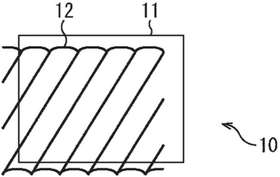
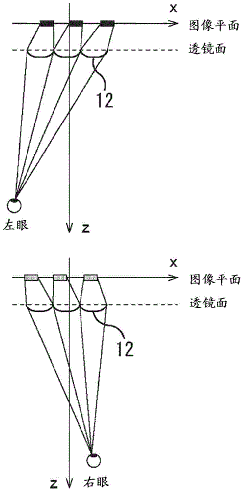
[0111] Figure 10 The image processing apparatus 100 is configured to have a face detection unit 101, a coordinate calculation unit 102, a phase calculation unit 103, a blend ratio calculation unit 104, an L projection conversion unit 105, an R projection conversion unit 106, a blend processing unit 107, and a The display unit 108 of the lenticular lens 109 . The image processing apparatus 100 displays the left-eye image and the right-eye image in a mixed manner based on the viewer's viewing position.
[0112] Specifically, the face detection unit 101 of the image processing apparatus 100 images a viewer to acquire an image of the viewer. The face detection unit 101 detects a face image from an image of a viewer, and detects a middle position of eyebrows from the face image. The face detectio...
no. 2 example
[0253]
[0254] Figure 33 is a block diagram showing a configuration example of the second embodiment of the image processing apparatus to which the present technology is applied.
[0255] The same reference numerals are given Figure 33 shown with Figure 10 The constituent elements of the same constituent elements. Duplicated descriptions will be appropriately omitted.
[0256] Figure 33The configuration of the image processing device 150 and Figure 10 The configuration of the image processing apparatus 100 is different in that instead of the face detection unit 101, the mixture ratio calculation unit 104, the L projection conversion unit 105, and the R projection conversion unit 106, a face detection unit 151, a mixture ratio calculation unit 158, L projection conversion unit 159 and R projection conversion unit 160, coordinate calculation unit 152 and coordinate calculation unit 155 are provided instead of coordinate calculation unit 102, phase calculation unit 1...
no. 3 example
[0379]
[0380] Figure 55 is a block diagram showing a configuration example of the third embodiment of the image processing apparatus to which the present technology is applied.
[0381] The same reference numerals are given Figure 55 shown with Figure 33 The constituent elements of the same constituent elements. Duplicated descriptions will be appropriately omitted.
[0382] Figure 55 The configuration of the image processing device 210 and Figure 33 The difference in the configuration of the image processing apparatus of , is that a blending processing unit 211 is provided instead of the blending ratio calculation unit 158 and the blending processing unit 107 . The image processing device 210 combines the left-eye image and the right-eye image based on the area ratio area_1 and the area ratio area_r using an expression in consideration of visual characteristics.
[0383] Specifically, the blend processing unit 211 of the image processing device 210 uses an ex...
PUM
 Abstract
Description
Claims
Application Information
 - R&D Engineer
- R&D Manager
- IP Professional
- Industry Leading Data Capabilities
- Powerful AI technology
- Patent DNA Extraction
Browse by: Latest US Patents, China's latest patents, Technical Efficacy Thesaurus, Application Domain, Technology Topic, Popular Technical Reports.
© 2024 PatSnap. All rights reserved.Legal|Privacy policy|Modern Slavery Act Transparency Statement|Sitemap|About US| Contact US: help@patsnap.com


