Remote-control cleaning machine

A cleaning machine and cleaning gun technology, which is applied in the field of cleaning machines, can solve the problems of increasing the cost and complexity of the manufacturing process, damaging the water pump and motor, endangering the safety of the operator, etc., achieving the effects of simple structure, prolonging the service life, and preventing accidents

Active Publication Date: 2014-06-18
ZHEJIANG SHUIMOLI ELECTROMECHANICAL EQUIP CO LTD
View PDF6 Cites 1 Cited by
  • Summary
  • Abstract
  • Description
  • Claims
  • Application Information

AI Technical Summary

Problems solved by technology

The existing cleaning machine mainly connects the water pump to the cleaning gun and then pressurizes the high-pressure water outlet. In order to adjust the output pressure of the pump head, it usually sets a pressure regulating valve at the water inlet and outlet. The function of the pressure regulating valve is to clean the cleaning gun Ensure the safety of the pump head and input power after work is completed and closed; however, the pressure regulating valve can only ensure the safety of the pump head and input power in a short period of time. If it takes a long time, the pressure in the connecting water pipe will be much higher. Due to the input pressure of the pump head when it is working normally and the temperature rise of the pump head itself, it is very likely to damage the water pump and the motor, which will not only cause damage to the equipment, but may even endanger the safety of the operator; moreover, the pressure regulating valve There is no doubt that it increases the cost of production and the complexity of the manufacturing process, so it is necessary to improve

Method used


Image

  • Remote-control cleaning machine
  • Remote-control cleaning machine
  • Remote-control cleaning machine

Examples


Embodiment Construction

[0015] The following descriptions are only preferred embodiments of the present invention, and do not limit the protection scope of the present invention. The present invention will be further described below in conjunction with the accompanying drawings and embodiments.

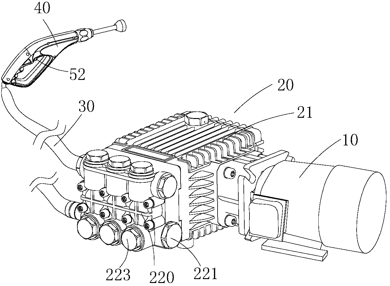
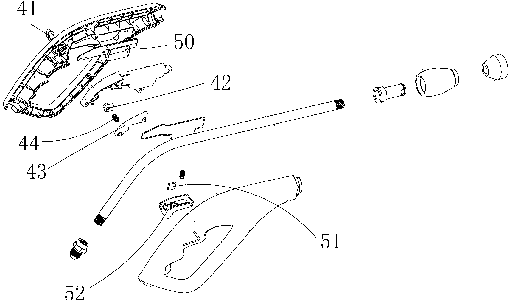
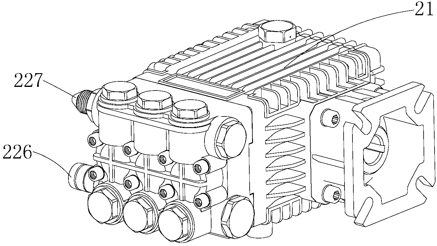
[0016] Examples, see Figure 1 to Figure 3 Shown: a remote cleaning machine, including a motor 10, a cleaning pump 20, a connecting water pipe 30, a frame and a cleaning gun 40, and the motor 10 and the cleaning pump 20 are fixed on the frame. The cleaning pump 20 includes a pump casing 21, a pump head 22 and a crankshaft connecting rod driving device arranged in the pump casing 21; the pump head 22 includes a cylinder body 220, a plug 221, a water sealing cap 223 and a water inlet and outlet valve; The water inlet and outlet valve 224 is arranged inside the cylinder body 220, and the plug 221 and the water sealing cap 223 cooperate with the drain port 225 on the cylinder body 220 respectively; The water ou...


PUM


Abstract

The invention discloses a remote-control cleaning machine. The remote-control cleaning machine comprises a motor, a cleaning pump, a connecting water pipe and a cleaning gun. The cleaning pump comprises a pump shell, a pump head and a crankshaft and connecting rod driving device. The crankshaft and connecting rod driving device is connected with the pump head and the motor. A remote-control receiver is arranged inside a power junction box of the motor and electrically connected with a power supply of the motor. The cleaning gun is connected with the pump head through the connecting water pipe, and a remote-control signal emitter matched with the remote-control receiver is arranged inside the cleaning gun. The remote-control cleaning machine has the advantages that the structure is simple, the motor can be controlled to stop working as long as a trigger is pulled after the using process of the cleaning gun is completed, the remote-control cleaning machine is convenient and safe to use, and the service life of the remote-control cleaning machine can be effectively prolonged. No pressure regulating valves are arranged on the pump head, so that cost is lower; locking of the trigger can be controlled through a locker, as a result, use security is enhanced when the cleaning gun is not in use, and an accident caused by the situation that someone pulls the trigger by accident is avoided.

Description

technical field [0001] The invention belongs to the technical field of washing machines, in particular to a remote-controlled washing machine. Background technique [0002] As a common equipment for car washing at present, the washing machine is mainly used for high-pressure water discharge to clean the vehicle. The existing cleaning machine mainly connects the water pump to the cleaning gun and then pressurizes the high-pressure water outlet. In order to adjust the output pressure of the pump head, it usually sets a pressure regulating valve at the water inlet and outlet. The function of the pressure regulating valve is to clean the cleaning gun Ensure the safety of the pump head and input power after work is completed and closed; however, the pressure regulating valve can only ensure the safety of the pump head and input power in a short period of time. If it takes a long time, the pressure in the connecting water pipe will be much higher. Due to the input pressure of the...

Claims


Application Information

Patent Timeline
Patent Type & Authority Applications(China)
IPC IPC(8): B60S3/04
Inventor 陈富林
Owner ZHEJIANG SHUIMOLI ELECTROMECHANICAL EQUIP CO LTD
Why Eureka
Try Eureka