
Safety anti-theft magnetic lock

A magnetic lock and safety technology, applied in building locks, locks controlled by non-mechanical transmission, buildings, etc., can solve problems such as unsafe, poor anti-theft effect, troublesome use, etc.

Active Publication Date: 2014-06-18
FOSHAN CHUANDONG MAGNETOELECTRICITY
View PDF5 Cites 4 Cited by
  • Summary
  • Abstract
  • Description
  • Claims
  • Application Information

AI Technical Summary

Problems solved by technology

[0004] The purpose of the present invention is to provide a safe anti-theft magnetic lock, which aims to solve the technical problems of poor anti-theft effect, troublesome use and unsafe factors in the traditional lock structure

Method used

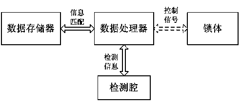

Image

  • Safety anti-theft magnetic lock
  • Safety anti-theft magnetic lock
  • Safety anti-theft magnetic lock

Examples


Embodiment 1

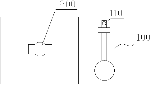
[0030] In this embodiment, the soft ferrite material prepared by sintering is used to make the identification piece, and the identification piece is fixed on the key, such as figure 1 As shown, an identification piece 110 is fixed on the key 100; the lock body is connected with a control system, and the control system includes a detection chamber, a data processor and a data storage. The detection chamber 200 is external (see figure 1 ), used for real-time detection of the identification piece 110 on the key 100; the data memory stores the full temperature range measurement data of the identification piece in advance (that is, the identification piece made of ferrite material is used as the iron core of the inductance element When setting, the inductance of the inductance element and the complete relationship curve data of the temperature); the data processor receives the real-time detection data, and compares and matches the real-time detection data with the measurement data ...

Embodiment 2

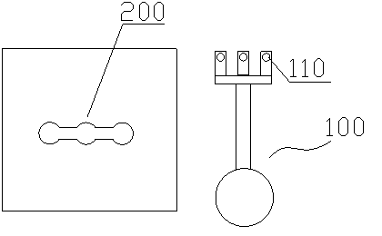
[0043] The detection method and specific settings of this embodiment are basically the same as those of Embodiment 1, the difference is that this embodiment discloses a more advanced magnetic lock structure, see image 3 , the key in this embodiment has three identification pieces (in actual use, the number of identification pieces can be increased according to specific needs), the detection chamber needs to detect these three identification pieces at the same time, the data processor obtains the detection result and It is matched with the data in the data memory, and if the matching is successful, the lock body acts to unlock.

[0044] In this embodiment, the database creation method is as follows:

[0045] S1. Use the soft ferrite material prepared by sintering to make multiple markers, and each key is equipped with 3 markers (the temperature curves of the three markers deliberately selected here are quite different, and their characteristic waveforms are completely differen...


PUM


Abstract

The invention discloses a safety anti-theft magnetic lock. The safety anti-theft magnetic lock comprises a key and a lock body. The key is provided with at least one marker, wherein physical characteristics of the markers change along with the temperature, and the changes are in an obvious repeated linear relation. A control system is connected to the lock body and comprises a detection cavity, a data processor and a data storage unit, wherein measurement data of the markers on the key are pre-stored in the data storage unit, the detection cavity detects the markers on the key inserted into the detection cavity and acquires detection data in real time, the data processor matches the detection data acquired by the detection cavity in real time with the measurement data pre-stored in the data storage unit in real time, and the lock body is controlled to act to achieve unlocking if matching is successful. According to the safety anti-theft magnetic lock, the unique physical characteristic curve of the markers serves as the key for unlocking, the uniqueness of the key is guaranteed, the safety of the lock is greatly guaranteed, and the lock is particularly suitable for protecting valuables or confidential data against theft.

Description

technical field [0001] The invention relates to an anti-theft lock structure, in particular to a safe anti-theft magnetic lock. Background technique [0002] There are a variety of lock structures on the market, including the most common tumbler locks, advanced electronic combination locks, and fingerprint locks. However, the anti-theft effect of traditional locks is poor. For the tumbler locks that use keys, the keys are easily copied; If the user keeps in mind the complex password number, it will be very troublesome if it is forgotten; the fingerprint is used as the electronic lock of the key, and the fingerprint is easily stolen, which is easy to unlock without the user's knowledge. Therefore utilize traditional lockset to protect valuables, important confidential information, there is great potential safety hazard. In addition, corresponding to enterprises, security agencies sometimes use and hand over the keys for some special reasons, so that the original security of...

Claims


Application Information

Patent Timeline
IPC IPC(8): E05B47/00
CPCE05B35/00E05B47/0045E05B2063/0091E05B35/001E05B2047/0083E05B2047/0084
Inventor 赵天安颜天宝龙克文
Owner FOSHAN CHUANDONG MAGNETOELECTRICITY
Learn More