
A high-efficiency energy-saving oxygen blowing device for mining furnace

A high-efficiency energy-saving technology for furnaces, applied in furnaces, furnace components, lighting and heating equipment, etc., can solve the problems of not enhancing the durability of oxygen blowing tubes, not being able to fully use up oxygen blowing tubes, and high production costs for oxygen enrichment alone , to achieve the effects of slow exhaustion, reduced energy consumption, and fast heating

Active Publication Date: 2015-11-18
鞍山东方竖炉直接还原铁有限公司
View PDF8 Cites 0 Cited by
  • Summary
  • Abstract
  • Description
  • Claims
  • Application Information

AI Technical Summary

Problems solved by technology

[0002] The oxygen lance used in the prior art has the following deficiencies: 1. In order to achieve the purpose of durability, the surface of the oxygen lance is usually coated with refractory mud or a refractory layer, but this method does not actually enhance the durability of the oxygen lance. 2. In actual use, the operator needs to hold the oxygen blowing tube close to the furnace body. Due to the high temperature of the furnace body and the fast melting speed of the oxygen blowing tube, the oxygen blowing tube is often not fully used. This results in a waste of oxygen blowing tubes
In addition, the traditional surface-coated oxygen blowing pipe, the surface coating is insulated from heat, and the oxygen cannot get physical heat. When the coating is heated through and the temperature of the steel pipe inside the coating exceeds 760°C, Fe and O2 react chemically, causing Fe Rapid burning, not to mention the physical heat of oxygen; 3. The connection method of muzzle jaws or pipe clamps is time-consuming to operate, which cannot better meet the time urgency requirements of the site, and is more likely to collapse due to the rapid increase of oxygen flow The danger of tempering; 4. The production cost of oxygen enrichment alone is high

Method used


Image

  • A high-efficiency energy-saving oxygen blowing device for mining furnace
  • A high-efficiency energy-saving oxygen blowing device for mining furnace
  • A high-efficiency energy-saving oxygen blowing device for mining furnace

Examples


Embodiment 1

[0017] A high-efficiency energy-saving oxygen blowing device for mining and metallurgy furnaces, including an oxygen blowing pipe body 1, the oxygen blowing pipe body 1 is a hollow pipe body formed by pressing a metal material, the hollow pipe body has a thick-walled small hole, and the diameter of the inner hole is 16mm. The wall thickness is 11mm.

[0018] The metal material used in the oxygen lance body 1 has the following chemical composition by mass percentage: 0.12% carbon, 0.27% silicon, 7% manganese, 0.01% phosphorus, 0.01% sulfur, 7.0% chromium, 0.02% molybdenum, and the balance For Fe.

Embodiment 2

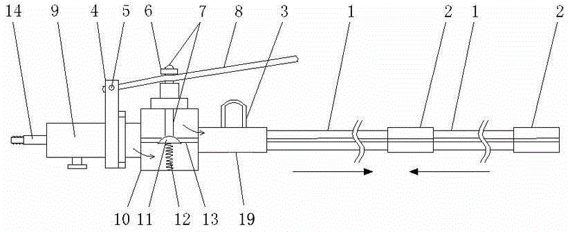
[0020] A high-efficiency energy-saving oxygen blowing device for mining and metallurgy furnaces, comprising an oxygen blowing pipe body 1, the oxygen blowing pipe body 1 is a hollow pipe body formed by pressing a metal material, and the hollow pipe body has a wall and other holes, and the diameter of the inner hole is 7mm. The wall thickness is 7mm.

[0021] The metal material used in the oxygen lance body 1 has the following chemical composition by mass percentage: 0.15% carbon, 0.28% silicon, 9% manganese, 0.02% phosphorus, 0.02% sulfur, 8.0% chromium, 0.022% molybdenum, and the balance For Fe.

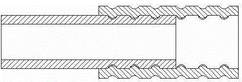
[0022] The end of the oxygen blowing pipe body 1 is provided with an oxygen blowing pipe supplementary body 2, the oxygen blowing pipe supplementary body 2 is a hollow pipe body, and the interference fit between the oxygen blowing pipe supplementary body 2 and the oxygen blowing pipe body 1, such as image 3 shown. The oxygen lance supplementary body 2 which is interference fit wi...

Embodiment 3

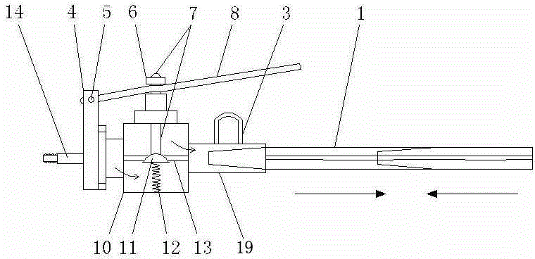
[0024] Such as figure 1 As shown, a high-efficiency energy-saving oxygen blowing device for mining and metallurgy furnaces includes an oxygen blowing pipe body 1. The oxygen blowing pipe body 1 is a hollow pipe body formed by pressing a metal material. The hollow pipe body has a thin wall and a large hole, and the diameter of the inner hole is It is 12mm and the wall thickness is 2mm.

[0025] The metal material used in the oxygen lance body 1 has the following chemical composition by mass percentage: 0.18% carbon, 0.29% silicon, 10% manganese, 0.035% phosphorus, 0.03% sulfur, 9.0% chromium, 0.025% molybdenum, and the balance For Fe.

[0026] The oxygen blowing tube body 1 is an oxygen blowing tube with a large and small head, and the two oxygen blowing tubes with small and large heads are connected in sequence from end to end and the joint adopts an interference fit.

[0027] The oxygen blowing pipe body 1 at the end is in interference fit with the oxygen lance muzzle 19 of...


PUM

PropertyMeasurementUnit
thicknessaaaaaaaaaa
diameteraaaaaaaaaa
pore sizeaaaaaaaaaa

Abstract

The invention provides an efficient energy-saving oxygen blowing device for a mining and metallurgy furnace. The efficient energy-saving oxygen blowing device comprises an oxygen blowing pipe body, wherein the wall thickness of the oxygen blowing pipe body is 1-20mm, and the diameter of the inner hole of the oxygen blowing pipe body is not less than 4mm. An oxygen blowing pipe reinforcing body which is in interference fit with the oxygen blowing pipe body is continuously in interference fit with another oxygen blowing pipe body or a connecting body of the oxygen blowing pipe body and the oxygen blowing pipe reinforcing body; or the oxygen blowing pipe body consists of two concentric reducer oxygen blowing pipes which are sequentially connected end to end, and interference fit is adopted at the joint; by virtue of additionally arranging a switch control connector and rich-poor oxygen fusion connector and adopting antioxidant elements Cr and Mo for the oxygen blowing pipe body, even when the temperature is greater than 760 DEG C, an oxygen blowing pipes still has higher antioxidant capability, so that by virtue of the high temperature resistant capability and heat-conducting capability of the pipes, O2 in the pipes can be heated, chemical heat and physical heat can be achieved in the furnace, and the service lives of the steel pipes are prolonged; furthermore, poor oxygen from air is added, so that oxygen is saved, and thus the purposes of high efficiency and energy conservation are achieved.

Description

technical field [0001] The invention relates to a high-efficiency energy-saving oxygen blowing device for a mining furnace. Background technique [0002] The oxygen lance used in the prior art has the following deficiencies: 1. In order to achieve the purpose of durability, the surface of the oxygen lance is usually coated with refractory mud or a refractory layer, but this method does not actually enhance the durability of the oxygen lance. 2. In actual use, the operator needs to hold the oxygen blowing tube close to the furnace body. Due to the high temperature of the furnace body and the fast melting speed of the oxygen blowing tube, the oxygen blowing tube is often not fully used. Therefore caused the waste of oxygen lance. In addition, the traditional surface-coated oxygen blowing pipe, the surface coating is insulated from heat, and the oxygen cannot get physical heat. When the coating is heated through and the temperature of the steel pipe inside the coating exceeds ...

Claims


Application Information

Patent Timeline
Patent Type & Authority Patents(China)
IPC IPC(8): F27D3/16
Inventor 张丽
Owner 鞍山东方竖炉直接还原铁有限公司
Learn More