Polarization SAR (Synthetic Aperture Radar) terrain radiation correction and geometric correction method based on imaging surface representation

A technology of terrain radiation correction and geometric correction, applied in the field of remote sensing image processing, to improve the accuracy of geometric correction, eliminate terrain effects, and improve the effect of terrain radiation correction

Active Publication Date: 2014-06-18
CHINESE ACAD OF SURVEYING & MAPPING
View PDF1 Cites 27 Cited by
  • Summary
  • Abstract
  • Description
  • Claims
  • Application Information

AI Technical Summary

Problems solved by technology

[0006] The purpose of the present invention is to solve the deficiencies of the existing topographic radiation correction and geometric correction methods, propose a polarization SAR topographic radiation correction and geometric correction method based on the imaging surface characterization, and derive the imaging surface as the backscattering coefficient characterization The expression conforms to the actual SAR imaging mechanism, and overcomes the serious radi

Method used


Image

  • Polarization SAR (Synthetic Aperture Radar) terrain radiation correction and geometric correction method based on imaging surface representation
  • Polarization SAR (Synthetic Aperture Radar) terrain radiation correction and geometric correction method based on imaging surface representation
  • Polarization SAR (Synthetic Aperture Radar) terrain radiation correction and geometric correction method based on imaging surface representation

Examples


Embodiment Construction

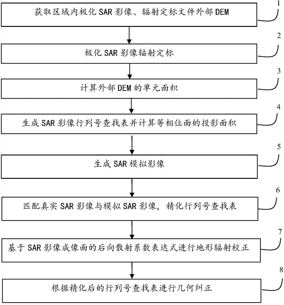
[0033] The present invention will be described in further detail below in conjunction with the accompanying drawings.

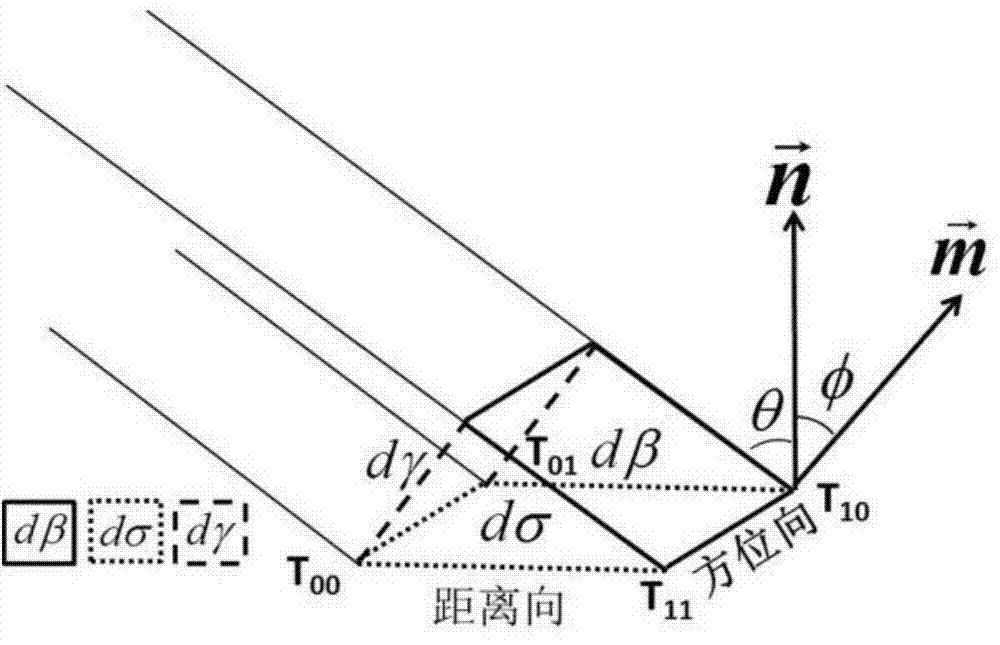
[0034] The backscatter coefficient is defined as the average radar cross-sectional area within a unit scattering area, which can be defined as β according to the difference of scattering units (dβ, dσ, dγ) 0 , σ 0 , γ 0 , dβ is the scattering unit of the imaging surface, indicating the size of the SAR image pixel, and its value is fixed, represented by a solid line box; dσ is the actual ground area corresponding to the SAR image pixel, called the ground scattering unit, and is represented by a solid dotted line box Indicates; dγ is the plane wave isophase surface scattering unit, which is represented by a dashed line frame. figure 2 medium vector is the normal of the imaging surface, the vector is the normal of the ground unit, and the angle (φ) between them is called the projection angle. vector The included angle (θ) with the SAR incident vector i...


PUM


Abstract

The invention relates to a polarization SAR (Synthetic Aperture Radar) terrain radiation correction and geometric correction method based on imaging surface representation. According to the method, the radiation value of the imaging surface of an SAR image is taken as the representation of a backscattering coefficient. The method comprises the following steps of 1, obtaining the SAR image and a radiation calibration file external DEM (Dynamic Effect Model) in a region; 2, performing radiation calibration according to a radiation calibration file of the original polarization SAR image; 3, calculating the unit area of the external DEM; 4, generating an SAR image line and column number lookup table according to a distance Doppler SAR positioning model and calculating the projection area of an equiphase surface; 5, generating an SAR simulation image by combining the projection area of the equiphase surface with the line and column number lookup table; 6, matching a real SAR image with the simulation SAR image, building a polynomial correction equation, and refining the line and column number lookup table; 7, carrying out terrain radiation correction on the polarization SAR image according to the backscattering coefficient expression based on the imaging surface of the SAR image; 8, carrying out geometric correction according to the refined line and column number lookup table. According to the scheme provided by the invention, the radiation distortion of the polarization SAR image, caused by terrain can be corrected, and the high-precision geometric positioning and correction of the polarization SAR image are realized.

Description

technical field [0001] The invention belongs to the field of remote sensing image processing, in particular to terrain radiation correction and geometric correction methods of side-looking radar remote sensing images including real aperture radar and synthetic aperture radar. Background technique [0002] Compared with traditional optical remote sensing data, Synthetic Aperture Radar (SAR) data can provide a large amount of ground object scattering characteristics and target polarization information, and has its own unique features in target detection, decomposition and parameter inversion. The advantages. However, due to the imaging characteristics of SAR itself and the influence of terrain fluctuations, SAR has serious radiation distortion, which leads to serious errors in the backscatter coefficient of the target. In the process of SAR imaging, various system and non-system factors directly or indirectly affect the backscatter coefficient. The premise of using the backs...

Claims


Application Information

Patent Timeline
IPC IPC(8): G01S7/40G01S13/90
CPCG01S7/024G01S7/40G01S13/90G01S13/9076
Inventor 张继贤卢丽君刘文祥黄国满杨书成
Owner CHINESE ACAD OF SURVEYING & MAPPING
Why Eureka
Try Eureka