
antenna structure

An antenna structure and antenna technology, applied in the direction of antenna coupling, radiating element structure, antenna support/installation device, etc., can solve the problem that the working frequency cannot be changed, and achieve the effect of meeting the communication requirements

Inactive Publication Date: 2018-10-30
SHENZHEN FUTAIHONG PRECISION IND CO LTD +1
View PDF7 Cites 0 Cited by
  • Summary
  • Abstract
  • Description
  • Claims
  • Application Information

AI Technical Summary

Problems solved by technology

However, once the antenna is printed on the board, its operating frequency cannot be changed

Method used


Image

  • antenna structure
  • antenna structure

Examples


Embodiment Construction

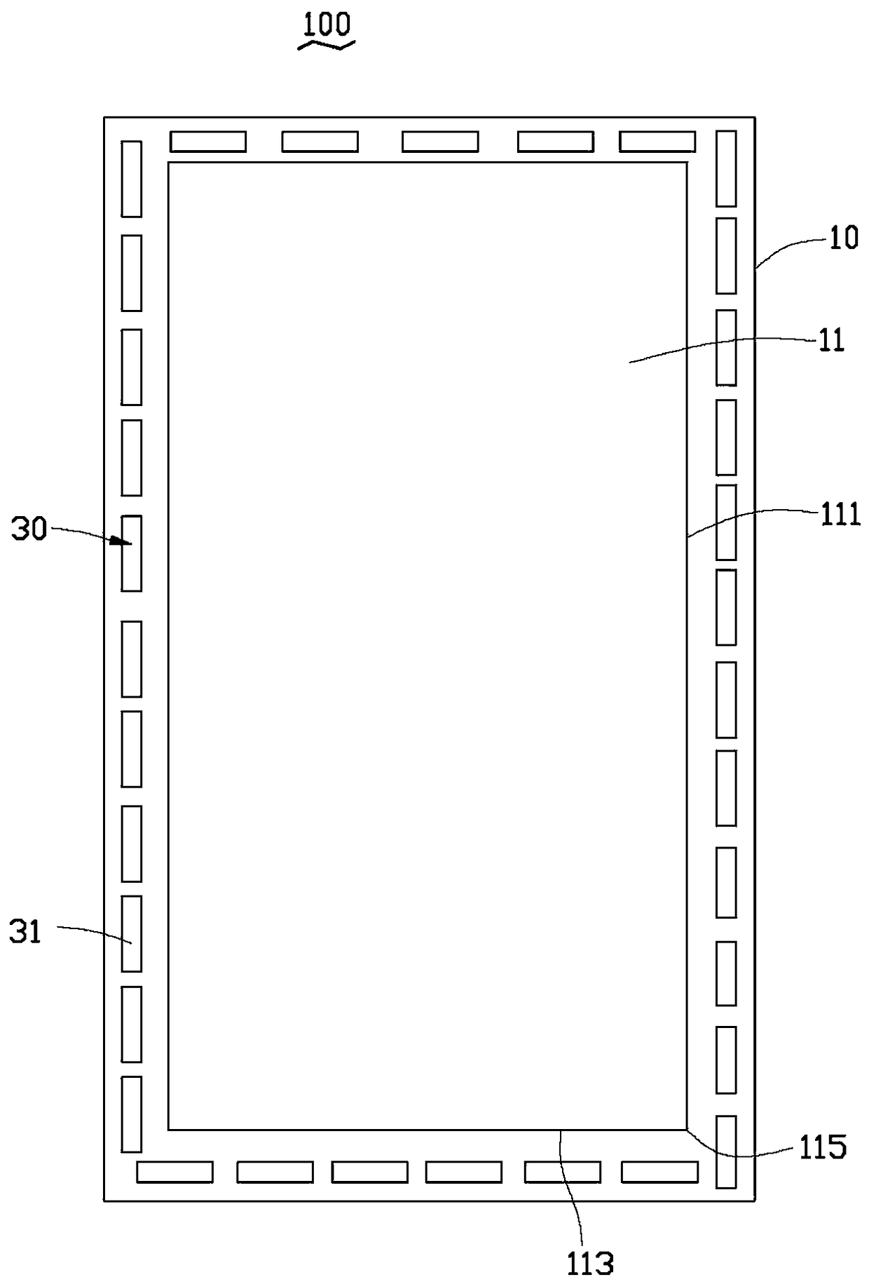
[0011] see figure 1 , the antenna structure 100 of the preferred embodiment of the present invention can be used in a wireless communication device such as a mobile phone for signal transmission and reception. The antenna structure 100 includes a circuit board 10 and an antenna unit 30 disposed on the circuit board 10 .

[0012] The circuit board 10 is a main board of a mobile phone and is roughly rectangular. The circuit board 10 is provided with a rectangular ground plane 11 . The ground plane 11 includes two long sides 111 and two short sides 113 , and the two long sides 111 connect with ends of the two short sides 113 to form four corners 115 .

[0013] The antenna unit 30 includes several radiators 31 . Each radiator 31 is substantially strip-shaped and printed on the circuit board 10 . The radiators 31 are arranged on the periphery of the ground plane 11 at regular intervals. In this preferred embodiment, the radiator 31 is surrounded by a rectangular frame, which i...


PUM


Abstract

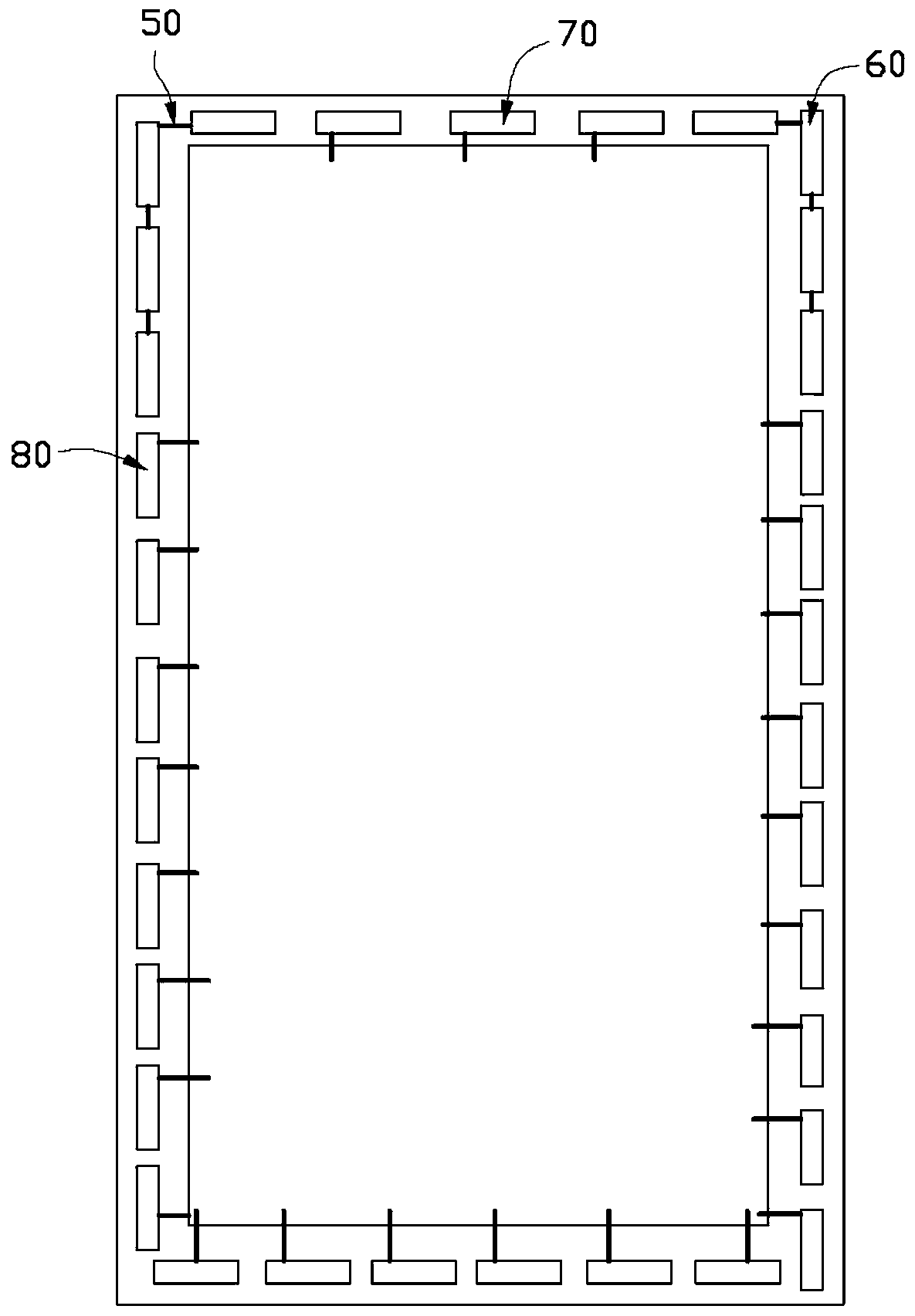
The invention discloses an antenna structure. The antenna structure comprises a circuit board and an antenna unit, wherein the antenna unit is arranged on the circuit board, the circuit board is provided with a ground plane, the antenna unit comprises radiating bodies, the radiating bodies are uniformly arranged at the periphery of the ground plane at intervals in a surrounding way, an antenna is formed by sequentially connecting parts of radiating bodies in series, and the working frequency of the antenna can be adjusted through changing the number of the radiating bodies which are connected in series.

Description

technical field [0001] The invention relates to an antenna structure, in particular to an antenna structure with adjustable working frequency. Background technique [0002] Wireless communication devices such as mobile phones are usually equipped with an antenna, and transmit and receive radio waves through the antenna to transmit and exchange radio data signals. In the prior art, in order to reduce the manufacturing cost of the wireless communication device and facilitate the miniaturization of the wireless communication device, the antenna is usually printed on the circuit board. However, once the antenna is printed on the circuit board, its operating frequency cannot be changed. Contents of the invention [0003] In view of the above problems, it is necessary to provide an antenna structure with adjustable working frequency. [0004] An antenna structure, which includes a circuit board and an antenna unit arranged on the circuit board, the circuit board is provided wi...

Claims


Application Information

Patent Timeline
Patent Type & Authority Patents(China)
IPC IPC(8): H01Q1/38H01Q1/22H01Q1/52
Inventor 陈亚男王晓冬
Owner SHENZHEN FUTAIHONG PRECISION IND CO LTD
Learn More