Novel jumper conductor clamper

A new type of drainage clamp, applied in the direction of clamping/spring connection, electrical components, circuits, etc., can solve the problems of high cost and inconvenient operation, and achieve the effects of low cost, convenient operation, and easy-to-master working methods

Inactive Publication Date: 2014-06-18
STATE GRID SHANDONG ELECTRIC POWER +1
View PDF1 Cites 4 Cited by
  • Summary
  • Abstract
  • Description
  • Claims
  • Application Information

AI Technical Summary

Problems solved by technology

[0004] For this reason, what the present invention aims to solve is the technical problem of inconvenient operation and high cost caused by the existing drainage wire clips

Method used


Image

  • Novel jumper conductor clamper
  • Novel jumper conductor clamper

Examples


Embodiment 1

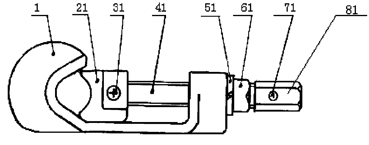
[0046] A specific embodiment of a novel drain wire clip of the present invention is given below, see figure 1 As shown, a new type of drain clamp includes: a drain clamp main body 1; a first pressing block 21, which cooperates with the drain clamp main body 1 to form a first clamping area for clamping wires; a first driving device, which drives The first pressing block 21 moves toward or away from the main body 1 of the drain wire clamp to form different clamping areas for clamping wires of different thicknesses.

[0047]The first driving device includes: a first stud; an installation hole with an internal thread provided on the main body of the drainage clamp, and the first stud is screwed into the installation hole with an internal thread Or unscrew to move on the main body 1 of the drainage clamp; the first fastener is used to clamp the first pressing block and the first stud; The first elastic buffer; the first locking member arranged on the first stud; the first rotating...

Embodiment 2

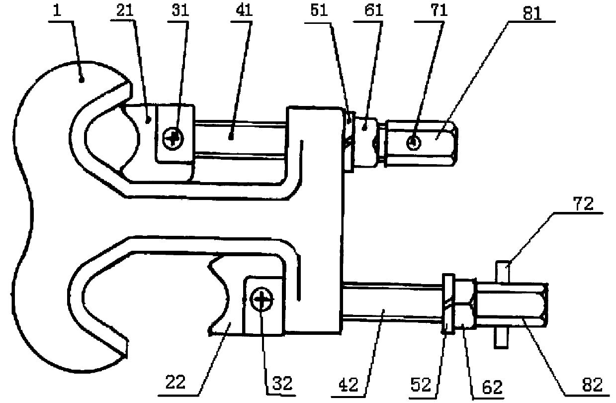
[0051] On the basis of above-mentioned embodiment 1, refer to figure 2 As shown, the drain clamp also includes a second pressing block, which cooperates with the main body of the drain clamp to form a second clamping area for clamping wires; a second driving device drives the second pressing block closer to or away from The direction movement of the main body of the drainage wire clamp forms different clamping areas for clamping different wires.

[0052] The second driving device includes: a second stud; a mounting hole with an internal thread provided on the main body of the drainage clamp, and the second stud is screwed into or Unscrewing can move on the main body of the drain clamp; the second fastener is used to clamp the second pressing block and the second stud; the second elastic buffer arranged on the second stud ; the second locking member arranged on the second stud; the second rotating member, arranged at the end of the second stud away from the second pressing bl...


PUM


Abstract

The invention provides a novel jumper conductor clamper, which comprises a jumper conductor clamper main body, a first pressing block and a first driving device, wherein the first pressing block is matched with the jumper conductor clamper main body for forming a first area for clamping a conductor, and the first driving device drives the first pressing block to move towards the direction close to or far away from the jumper conductor clamper main body, so that different clamping areas for clamping different conductors are formed. For jumper conductors of different specifications, the first driving device can drive the first pressing block to move so as to change the size of the first clamping area for clamping the conductor between the pressing block and the jumper conductor clamper main body for clamping the jumper conductors of different specifications, the structure is simple, the cost is low, the operation is convenient and flexible, the novel jumper conductor clamper is suitable for being used on different conductor types and different materials on one jumper conductor, a working method is easy to master and popularize, and workers can operate the novel jumper conductor clamper only after being trained for a short term.

Description

technical field [0001] The invention relates to an electric fitting, in particular to a novel drainage clip. Background technique [0002] There are many ways to connect the power line pole and tower drain wire joints. During operation, the joints are often overheated due to poor line construction technology, overload operation, and different metal materials of the drain wires. If it is not handled in time, there will be an accident of breaking the drainage line, causing a power outage on the power line and affecting the safe and stable operation of the power grid. At present, when dealing with the overheating of the drain wire, the drain wire clamp is generally used for power outage operation or equipotential treatment. [0003] Chinese patent document CN2535933Y provides a new type of live drain wire clip, which has a clamping hook, a clamping plate and a tightening screw, and a special clamping device for clamping and connecting the drain wire and the clamping hook to ea...

Claims


Application Information

Patent Timeline
IPC IPC(8): H01R11/14H01R4/38
Inventor 乔绪山王泽众
Owner STATE GRID SHANDONG ELECTRIC POWER
Why Eureka
Try Eureka