
Power supply with switch control function

A switching control and power supply technology, applied in electronic switches, electrical components, pulse technology, etc., can solve problems such as unrealistic, error-prone, inability to realize on-delay and off-delay, and achieve the effect of simple application

Active Publication Date: 2014-06-18
RIGOL
View PDF3 Cites 6 Cited by
  • Summary
  • Abstract
  • Description
  • Claims
  • Application Information

AI Technical Summary

Problems solved by technology

[0007] When repeated power-on and power-off operations are required for a long time, although the control power output is in two states: on and off, when the number of repetitions increases, the user will manually configure them one by one, which will cause a large workload and waste manpower; In addition, the operation will be tedious and error-prone, which is obviously unrealistic
It is a better method to implement through remote interface programming, but this method involves various software and hardware environments such as remote interface programming, PC, connection cables, etc. When one of them is missing, it cannot be realized, and through The remote interface sends commands to realize the switch. The time of sending commands is affected by various software and hardware environments such as the current operating environment of the PC, cables, interfaces, etc., and it is impossible to achieve accurate on-delay and off-delay.

Method used


Image

  • Power supply with switch control function
  • Power supply with switch control function
  • Power supply with switch control function

Examples


Embodiment Construction

[0036] In order to make the purpose, technical solutions and advantages of the embodiments of the present invention clearer, the technical solutions in the embodiments of the present invention will be clearly and completely described below in conjunction with the drawings in the embodiments of the present invention. Obviously, the described embodiments It is a part of embodiments of the present invention, but not all embodiments. Based on the embodiments of the present invention, all other embodiments obtained by persons of ordinary skill in the art without making creative efforts belong to the protection scope of the present invention.

[0037] The purpose of the embodiments of the present invention is to:

[0038] The existing technology cannot better meet the special application requirements of repeated power-on and power-off, so the embodiment of the present invention designs an automatic switch control device to meet the following requirements:

[0039] 1. The need to re...


PUM


Abstract

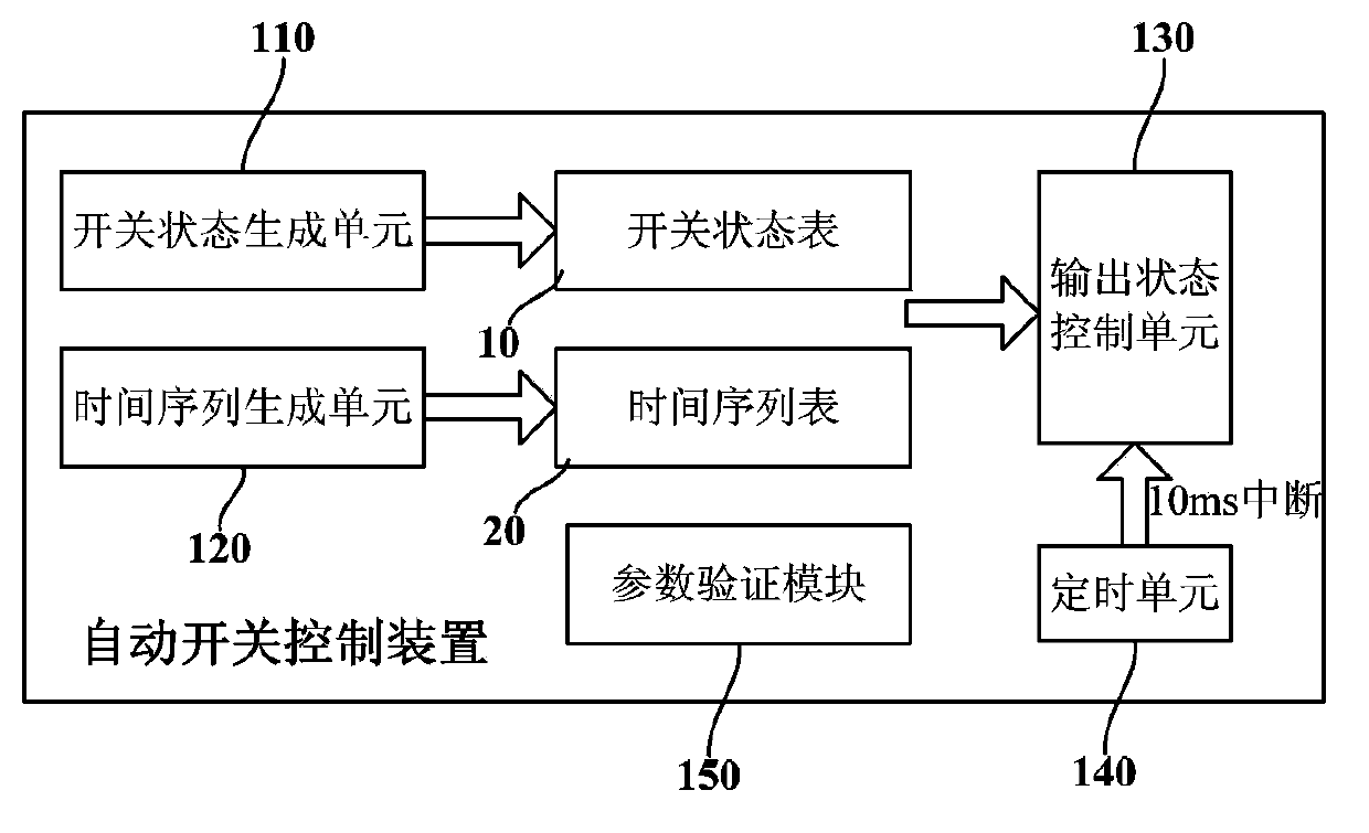
The embodiment of the invention provides a power supply with a switch control function. The power supply comprises an automatic switch control device. The automatic switch control device comprises a switch state editing unit, a time sequence generating unit, and an output state control unit, wherein the switch state editing unit is used for generating a switch sequence composed for a plurality of groups of switch states and a switch state table is obtained according to the switch sequence; the time sequence generating unit is used for generating a time sequence composed of a plurality of groups of delay time and a time sequence table is obtained according to the generated time sequence; mapping relationship exists in each switch state group and each delay time group; and the output state control unit is used for controlling on or off of power supply output signals in the corresponding time according to each switch state group and each delay time group in mapping relationship in the switch state table and the time sequence table. The power supply has the advantages of saving manpower, avoiding errors of manual operation, and realizing accurate delay opening and delay closing control.

Description

technical field [0001] The invention relates to the technical field of general electronic measurement and testing, in particular to a power supply with switch control function. Background technique [0002] As an indispensable tool in electronic design, linear DC power supply can work not only as a power supply, but also as a measuring device. It is widely used in various fields such as laboratories, scientific research units, and industries. With the digitalization of electronic devices becoming more and more common, the original linear analog power supply will gradually be replaced by digital power supply. Digital power supply has the characteristics of good scalability, lower cost, simpler circuit, easy mass production, and stable performance. Usually have voltage, current continuously adjustable function, and output switch function. [0003] The control of the output switch is divided into two categories. One is to directly disconnect the connection physically by adding...

Claims


Application Information

Patent Timeline
IPC IPC(8): H03K17/28
Inventor 叶群松王悦王铁军李维森
Owner RIGOL
Learn More